8-48 System Upgrade
17.
Press the POWER switch to power on the module.
18.
Verify that POST displays no error messages.
If POST displays an error message, take a note on the massage and see the POST error
messages listed in Chapter 7.
19.
To operate a multi-processor system, do the following:
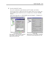
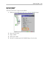
If in “Computer” of Device Manager, [Driver] is set to “ACPI single processor PC,”
change it to “ACPI multi-processor PC” and restart the server to update the system.
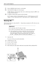
Removing CPU
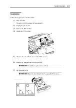
Follow the steps below to remove the CPU. Except when you replace the CPU with a new one,
power off the server.
IMPORTANT:
Do not remove the CPU unless it is faulty.
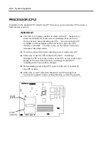
If a CPU is not mounted on CPU#2, cover it with an anti-dust sheet.
After operation, the cool sheet at the bottom of the heat sink may
stick to the CPU because of heat. When you dismount the heat
sink, turn it lightly to make sure that the heat sink is not sticking to
the CPU. Otherwise, the CPU or socket may be damaged.
1.
Shut down OS.
The server will be powered off automatically.
2.
Unplug the power cord.
3.
Remove the CPU module.
4.
Detach the CPU air duct.
5.
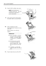
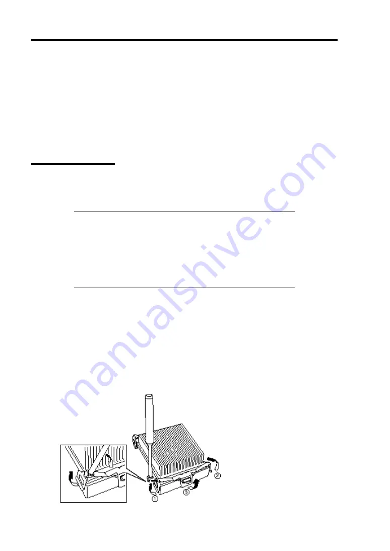
Dismount the heat sink using the dismount tool included with the additional CPU.
Summary of Contents for Express5800/320Lb FT Linux
Page 10: ...iv This page is intentionally left blank ...
Page 16: ...x This page is intentionally left blank ...
Page 19: ...Precautions for Use 1 3 Label A Label B Label C Label E Label D ...
Page 20: ...1 4 Precautions for Use Rack mount model Label B Label A Label C Label D ...
Page 21: ...Precautions for Use 1 5 Label D Label C Label B Label A ...
Page 22: ...1 6 Precautions for Use PCI CPU Modules PCI Module CPU Module Label A Label A Label A ...
Page 36: ...1 20 Precautions for Use This page is intentionally left blank ...
Page 44: ...2 8 General Description Front View inside Tower model Rack mount model ...
Page 70: ...2 34 General Description This page is intentionally left blank ...
Page 118: ...3 48 Setup This page is intentionally left blank ...
Page 162: ...4 44 System Configuration This page is intentionally left blank ...
Page 294: ...6 14 Maintenance This page is intentionally left blank ...
Page 336: ...7 42 Troubleshooting This page is intentionally left blank ...
Page 355: ...System Upgrade 8 19 15 Check the disk you selected and click Next 16 Click Complete ...
Page 399: ...System Upgrade 8 63 Cable ties included with cabinet ...
Page 410: ...8 74 System Upgrade This page is intentionally left blank ...
Page 412: ...A 2 Specifications This page is intentionally left blank ...


