8-62 System Upgrade
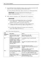
10.
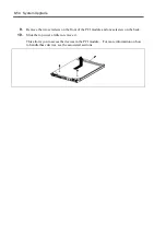
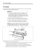
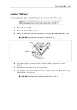
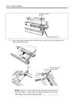
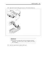
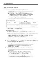
In the case of a long board, slide the bracket to fasten the other edge of the board.
11.
Install the PCI module cover.
12.
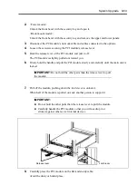
Install the PCI module.
13.
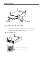
Connect the network cable and option cables.
14.
Close the release lever.
15.
Secure the release lever with the setscrew.
16.
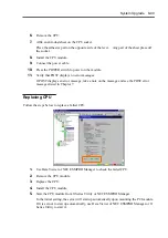
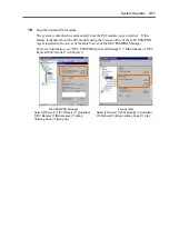
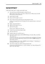
Boot the PCI module using the NEC ESMPRO Manager or ft series utility to establish a
dual configuration.
In the initial setting, the server will start up automatically upon mounting the PCI module.
If it is set not to start up automatically, use Data Viewer of NEC ESMPRO Manager or ft
Series Utility to start it.
For more information, refer to "NEC ESMPRO Agent and Manager" - "Maintenance of
NEC Express5800/ft series" in Chapter 5.
17.
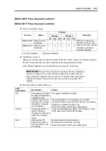
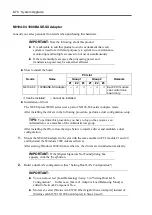
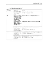
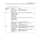
Check the PCI module status LED and PCI board status LED.
For description of LED indications, see “LED” in Chapter 2 and “Setup of Optional PCI
Board” later in this chapter.
18.
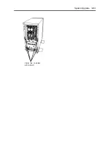
Use cable ties to fasten the extra length of cables.
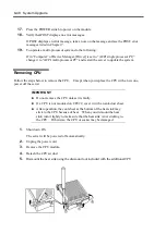
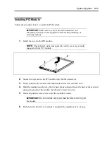
Screw
Bends for fastening
boards
Summary of Contents for Express5800/320Lb FT Linux
Page 10: ...iv This page is intentionally left blank ...
Page 16: ...x This page is intentionally left blank ...
Page 19: ...Precautions for Use 1 3 Label A Label B Label C Label E Label D ...
Page 20: ...1 4 Precautions for Use Rack mount model Label B Label A Label C Label D ...
Page 21: ...Precautions for Use 1 5 Label D Label C Label B Label A ...
Page 22: ...1 6 Precautions for Use PCI CPU Modules PCI Module CPU Module Label A Label A Label A ...
Page 36: ...1 20 Precautions for Use This page is intentionally left blank ...
Page 44: ...2 8 General Description Front View inside Tower model Rack mount model ...
Page 70: ...2 34 General Description This page is intentionally left blank ...
Page 118: ...3 48 Setup This page is intentionally left blank ...
Page 162: ...4 44 System Configuration This page is intentionally left blank ...
Page 294: ...6 14 Maintenance This page is intentionally left blank ...
Page 336: ...7 42 Troubleshooting This page is intentionally left blank ...
Page 355: ...System Upgrade 8 19 15 Check the disk you selected and click Next 16 Click Complete ...
Page 399: ...System Upgrade 8 63 Cable ties included with cabinet ...
Page 410: ...8 74 System Upgrade This page is intentionally left blank ...
Page 412: ...A 2 Specifications This page is intentionally left blank ...

