8-70 System Upgrade
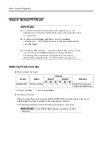
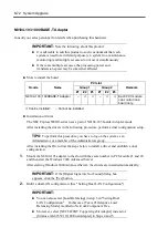
N8104-84 1000BASE-SX Adapter
Consult your sales personnel for details when purchasing this hardware.
IMPORTANT:
Note the following about this product:
It is advisable to add this product to such environment that each
system is used for a different purpose (ex. system line, maintenance,
monitoring) and multiple accesses do not occur simultaneously.
If there are multiple accesses, the processing power and
transmission speed may be somewhat affected.
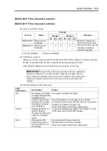
Slots to install the board
PCI slot
Group 1
Group 2
N code
Name
#1 #2
#3
#1
#2
#3
Remarks
N8104-84 1000BASE-SX
Adapter –
√
√
–
√
√
Each PCI module
can contain one
board only.
√
: Can be installed. –: Cannot be installed.
Installation of driver
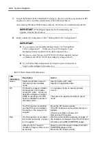
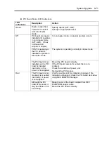
The NEC Express5800/ft series uses a pair of N8104-84 boards in duplex mode.
After installing the drivers in the following procedure, perform a dual configuration setup.
TIPS:
To perform this procedure, you have to log on the system as an
Administrator or a member of the Administrators group.
After installing the OS, follow the steps below to install a driver and establish a dual
configuration:
1.
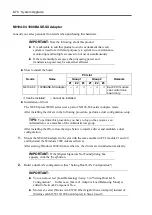
Mount the N8104-84 adapter to the slot with the same number in PCI module #1 and #2,
and then start the Windows 2000 Advanced Server.
After starting Windows 2000 Advanced Server, the drivers are installed automatically.
IMPORTANT:
If the [Digital Signature Not Found] dialog box
appears, click the [Yes] button.
2.
Build a dual LAN configuration. (See "Setting Dual LAN Configuration")
IMPORTANT:
You can also select [Load Balancing] in step 3 in "Setting Dual LAN
Configuration". In this case, [Team #1:Adaptive Load Balancing Mode] is
added to Network Component Tree.
Moreover, select [Stratus AA-U5700 Fiber Gigabit Server Adapter] instead of
[Stratus emb-82559 10/100 Enet Adapter] in Steps 4 and 5.
Summary of Contents for Express5800/320Lb FT Linux
Page 10: ...iv This page is intentionally left blank ...
Page 16: ...x This page is intentionally left blank ...
Page 19: ...Precautions for Use 1 3 Label A Label B Label C Label E Label D ...
Page 20: ...1 4 Precautions for Use Rack mount model Label B Label A Label C Label D ...
Page 21: ...Precautions for Use 1 5 Label D Label C Label B Label A ...
Page 22: ...1 6 Precautions for Use PCI CPU Modules PCI Module CPU Module Label A Label A Label A ...
Page 36: ...1 20 Precautions for Use This page is intentionally left blank ...
Page 44: ...2 8 General Description Front View inside Tower model Rack mount model ...
Page 70: ...2 34 General Description This page is intentionally left blank ...
Page 118: ...3 48 Setup This page is intentionally left blank ...
Page 162: ...4 44 System Configuration This page is intentionally left blank ...
Page 294: ...6 14 Maintenance This page is intentionally left blank ...
Page 336: ...7 42 Troubleshooting This page is intentionally left blank ...
Page 355: ...System Upgrade 8 19 15 Check the disk you selected and click Next 16 Click Complete ...
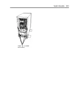
Page 399: ...System Upgrade 8 63 Cable ties included with cabinet ...
Page 410: ...8 74 System Upgrade This page is intentionally left blank ...
Page 412: ...A 2 Specifications This page is intentionally left blank ...

