General Description 2-11
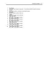
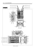
1 Serial
port
A
connector
Connected to a device that has a serial interface. For maintenance use only.
2 AC
inlet
PC socket for plugging a power cord.
3
Serial port B connector
Connected to a device that has a serial interface. For maintenance use only.
4
USB connector 1 (top)/USB connector 2 (bottom)
Connected to devices that support the USB interface.
Connect the mouse to USB 1; connect the keyboard to USB 2.
5 AC
inlet
PC socket for plugging a power cord.
6 Monitor
connector
Connected to the display unit.
7 SCSI
connector
Used for connecting external SCSI devices.
8
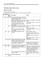
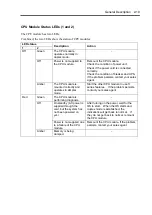
PCI module status LED 1
See “LEDs” in this chapter for details.
9
PCI module status LED 2
See “LEDs” in this chapter for details.
10
PCI board slot status LED (Slot1)
See “LEDs” in this chapter for details.
11
PCI board slot status LED (Slot2)
See “LEDs” in this chapter for details.
12
PCI board slot status LED (Slot3)
See “LEDs” in this chapter for details.
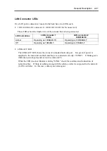
13 LINK/ACT
LED
See “LEDs” in this chapter for details.
14
LAN connector 2
A connector for 1000BASE-TX, 100BASE-TX, and 10BASE-T. Connected to the network
system on LAN.
15 100/10
LED
See “LEDs” in this chapter for details.
16 LINK/ACT
LED
See “LEDs” in this chapter for details.
17 100/10
LED
See “LEDs” in this chapter for details.
18
LAN connector 1
A connector for 100BASE-TX and 10BASE-T. Connected to the network system on LAN.
Summary of Contents for Express5800/320Lb FT Linux
Page 10: ...iv This page is intentionally left blank ...
Page 16: ...x This page is intentionally left blank ...
Page 19: ...Precautions for Use 1 3 Label A Label B Label C Label E Label D ...
Page 20: ...1 4 Precautions for Use Rack mount model Label B Label A Label C Label D ...
Page 21: ...Precautions for Use 1 5 Label D Label C Label B Label A ...
Page 22: ...1 6 Precautions for Use PCI CPU Modules PCI Module CPU Module Label A Label A Label A ...
Page 36: ...1 20 Precautions for Use This page is intentionally left blank ...
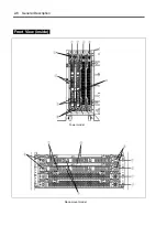
Page 44: ...2 8 General Description Front View inside Tower model Rack mount model ...
Page 70: ...2 34 General Description This page is intentionally left blank ...
Page 118: ...3 48 Setup This page is intentionally left blank ...
Page 162: ...4 44 System Configuration This page is intentionally left blank ...
Page 294: ...6 14 Maintenance This page is intentionally left blank ...
Page 336: ...7 42 Troubleshooting This page is intentionally left blank ...
Page 355: ...System Upgrade 8 19 15 Check the disk you selected and click Next 16 Click Complete ...
Page 399: ...System Upgrade 8 63 Cable ties included with cabinet ...
Page 410: ...8 74 System Upgrade This page is intentionally left blank ...
Page 412: ...A 2 Specifications This page is intentionally left blank ...

