2-16 General Description
LEDs
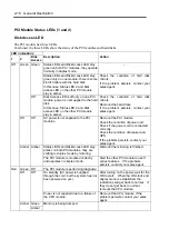
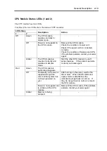
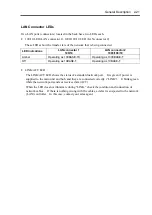
This section describes indications and meanings of the LEDs on NEC Express5800/ft series.
POWER LED
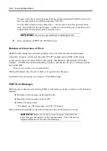
The POWER switch of the PCI module also functions as a POWER LED. When power is
supplied to the modules, POWER LED on the primary side will illuminate (the switch also works
on the primary side alone).
BMC Status LED
The BMC Status LED indicates the status of the Baseboard Management Controller (BMC)
installed on NEC Express5800/ft series.
The LED stays green while the server is running normally. If the LED is not green, there is
something wrong with the server.
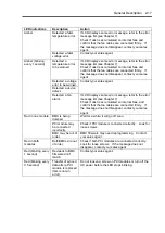
The table below shows indications of the BMC Status LED and their meanings.
Tips:
To determine the cause of trouble, use the NEC ESMPRO or the
Off-line Maintenance Utility to view the error log.
When you want to restart the server, perform a shutdown if the OS
allows you to shut down the system. If not, perform a reset or
forced shutdown, or you can restart the server by unplug and
plugging the power cord.
LED indications
Description
Action
Green
BMC operates
normally and CPU
and PCI modules
are in duplex
mode.
–
Green (blinking
every 1 second)
CPU or PCI
modules are not in
duplex mode
during operation.
Remount components whose Status LED is red. If
the problem persists, replace that module.
AC power is all off.
Turn on the AC power.
Performing POST.
Wait for a while; it will illuminate in green shortly after
POST.
CPU module error
occurred.
Off
PCI module error
occurred.
After turning off the power, turn it on to restart the
system. If some error message appears on the
POST screen, write it down and contact your sales
agent.
Summary of Contents for Express5800/320Lb FT Linux
Page 10: ...iv This page is intentionally left blank ...
Page 16: ...x This page is intentionally left blank ...
Page 19: ...Precautions for Use 1 3 Label A Label B Label C Label E Label D ...
Page 20: ...1 4 Precautions for Use Rack mount model Label B Label A Label C Label D ...
Page 21: ...Precautions for Use 1 5 Label D Label C Label B Label A ...
Page 22: ...1 6 Precautions for Use PCI CPU Modules PCI Module CPU Module Label A Label A Label A ...
Page 36: ...1 20 Precautions for Use This page is intentionally left blank ...
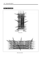
Page 44: ...2 8 General Description Front View inside Tower model Rack mount model ...
Page 70: ...2 34 General Description This page is intentionally left blank ...
Page 118: ...3 48 Setup This page is intentionally left blank ...
Page 162: ...4 44 System Configuration This page is intentionally left blank ...
Page 294: ...6 14 Maintenance This page is intentionally left blank ...
Page 336: ...7 42 Troubleshooting This page is intentionally left blank ...
Page 355: ...System Upgrade 8 19 15 Check the disk you selected and click Next 16 Click Complete ...
Page 399: ...System Upgrade 8 63 Cable ties included with cabinet ...
Page 410: ...8 74 System Upgrade This page is intentionally left blank ...
Page 412: ...A 2 Specifications This page is intentionally left blank ...

