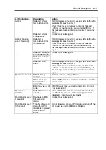
2-20 General Description
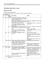
PCI Board Slot Status LEDs (P1, P2, P3)
To show the status of PCI board slots, each PCI module has three status LEDs.
LED
indications
Description Action
PCI board is mounted
correctly and operates
in duplex mode.
The system operates normally.
Off
The PCI board is not
mounted; is mounted
incorrectly; or power
is not supplied.
If the PCI board is not mounted or is mounted
incorrectly, just mount it correctly; there is no problem.
Check the condition of power unit.
If the problem persists, contact your sales agent.
Amber
Performing POST; or
the PCI board is
mounted correctly and
operates in simplex
mode.
Simplex mode is not a problem.
To use ft series features, attach a PCI board to a slot
of the same on the other PCI module.
Red
Although the PCI
board is mounted, it
may be offline or not
be working.
Remount the PCI board correctly.
Remount the PCI module correctly.
If the problem persists, contact your sales agent.
For LED indications when option boards are attached, see “PCI Module” in Chapter 8.
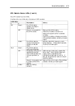
Hard Disk LED
A hard disk LED shows the status of hard disks that are mounted in the 3.5-inch device bay.
Combined, the two hard disk LEDs on PCI modules 1 and 2 show the status of the hard disks.
PCI
module 1
PCI
module 2
Description Action
Green Green Hard disks are mirrored and
operate normally.
–
Green Amber Some trouble occurred on the hard
disk of the PCI module 1.
The hard disk on the PCI module 2
is operating without mirroring.
Check the condition of hard disk
mirrors.
If the problem persists, contact
your sales agent.
Amber Amber Hard disk mirroring is being
performed.
Wait until the mirroring is
finished.
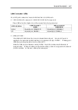
Tips:
When there are many accesses, the access LED will blink frequently.
Check if the LED blinks in green when the number of accesses
decreases, or if it is green when there are no accesses anymore.
When you power on NEC Express5800/ft series and the access
LEDs do not illuminate green, remount the hard disks.
Summary of Contents for Express5800/320Lb FT Linux
Page 10: ...iv This page is intentionally left blank ...
Page 16: ...x This page is intentionally left blank ...
Page 19: ...Precautions for Use 1 3 Label A Label B Label C Label E Label D ...
Page 20: ...1 4 Precautions for Use Rack mount model Label B Label A Label C Label D ...
Page 21: ...Precautions for Use 1 5 Label D Label C Label B Label A ...
Page 22: ...1 6 Precautions for Use PCI CPU Modules PCI Module CPU Module Label A Label A Label A ...
Page 36: ...1 20 Precautions for Use This page is intentionally left blank ...
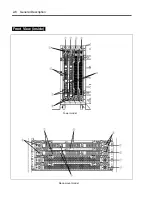
Page 44: ...2 8 General Description Front View inside Tower model Rack mount model ...
Page 70: ...2 34 General Description This page is intentionally left blank ...
Page 118: ...3 48 Setup This page is intentionally left blank ...
Page 162: ...4 44 System Configuration This page is intentionally left blank ...
Page 294: ...6 14 Maintenance This page is intentionally left blank ...
Page 336: ...7 42 Troubleshooting This page is intentionally left blank ...
Page 355: ...System Upgrade 8 19 15 Check the disk you selected and click Next 16 Click Complete ...
Page 399: ...System Upgrade 8 63 Cable ties included with cabinet ...
Page 410: ...8 74 System Upgrade This page is intentionally left blank ...
Page 412: ...A 2 Specifications This page is intentionally left blank ...


