2-24 General Description
Power ON
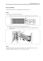
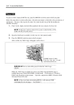
To power on NEC Express5800/ft series, press the POWER switch located on the front panel.
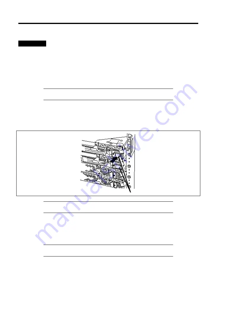
Follow the steps below to turn on the power. (A rack-mount model is shown here for convenience of
explanation. However, the steps are the same for a tower model except that the modules are
mounted vertically.)
1.
Power on the display unit and other peripheral devices connected to the server.
NOTE:
If the power cord is connected to a power controller like a UPS,
make sure that it is powered on.
2.
Open the front bezel (or detach it in the case of a rack-mount model).
3.
Press the POWER switch located on the front panel.
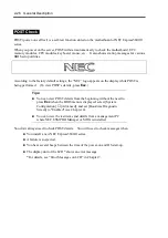
After a while, the "NEC" logo will appear on the screen.
IMPORTANT:
Do not turn off the power before the "NEC" logo
appears.
While the "NEC" logo is displayed on the screen, NEC Express5800/ft series is
performing a power-on self test (POST) to check itself. For details, see "Check by
POST" described later in this manual. Upon the completion of POST, Windows 2000
Advanced Server will start.
NOTE:
If the server finds errors during POST, it will interrupt POST
and display the error message. See Chapter 7.
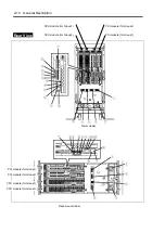
POWER switches* (LEDs)
*You can only use a power
switch whose LED is on.
Summary of Contents for Express5800/320Lb FT Linux
Page 10: ...iv This page is intentionally left blank ...
Page 16: ...x This page is intentionally left blank ...
Page 19: ...Precautions for Use 1 3 Label A Label B Label C Label E Label D ...
Page 20: ...1 4 Precautions for Use Rack mount model Label B Label A Label C Label D ...
Page 21: ...Precautions for Use 1 5 Label D Label C Label B Label A ...
Page 22: ...1 6 Precautions for Use PCI CPU Modules PCI Module CPU Module Label A Label A Label A ...
Page 36: ...1 20 Precautions for Use This page is intentionally left blank ...
Page 44: ...2 8 General Description Front View inside Tower model Rack mount model ...
Page 70: ...2 34 General Description This page is intentionally left blank ...
Page 118: ...3 48 Setup This page is intentionally left blank ...
Page 162: ...4 44 System Configuration This page is intentionally left blank ...
Page 294: ...6 14 Maintenance This page is intentionally left blank ...
Page 336: ...7 42 Troubleshooting This page is intentionally left blank ...
Page 355: ...System Upgrade 8 19 15 Check the disk you selected and click Next 16 Click Complete ...
Page 399: ...System Upgrade 8 63 Cable ties included with cabinet ...
Page 410: ...8 74 System Upgrade This page is intentionally left blank ...
Page 412: ...A 2 Specifications This page is intentionally left blank ...

