Setup 3-13
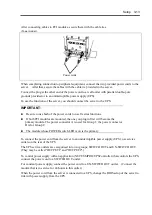
After connecting cables to PCI modules, secure them with the cable ties.
<Tower model>
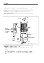
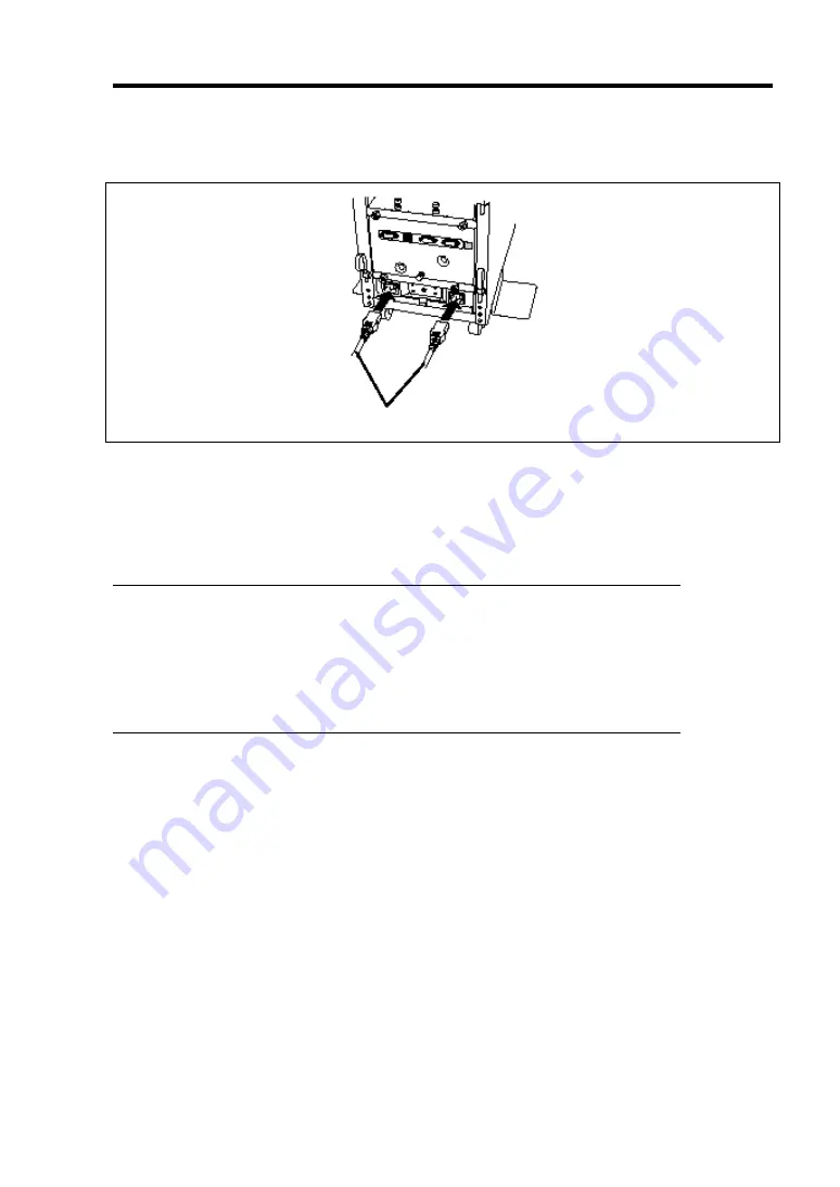
When completing connection to peripheral equipment, connect the two provided power cords to the
server. After that, secure the cables with the cable tie provided in the server.
Connect the plug at the other end of the power cord to a wall outlet with parallel double-pole
grounds provided or to an uninterruptible power supply (UPS).
To use the functions of the server, you should connect the server to the UPS.
IMPORTANT:
Be sure to use both of the power cords to use ft series functions.
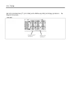
If both PCI modules are mounted, the one you plug in first will become the
primary module. The power connector A is used for Group 1; the power connector
B is for Group 2.
The module whose POWER switch LED is on is the primary.
To connect the power cord from the server to an uninterruptible power supply (UPS), use service
outlets on the rear of the UPS.
The UPS service outlets are categorized into two groups: SWITCH OUT and UN-SWITCH OUT.
(They may be called "OUTPUT1" and "OUTPUT2".)
To control power supply with an application (NEC ESMPRO/UPSController) that controls the UPS,
connect the power cord to a SWITCH OUT outlet.
For constant power supply, connect the power cord to a UN-SWITCH OUT outlet. (Connect the
modem that is in service for 24 hours to this outlet.)
When the power cord from the server is connected to a UPS, change the BIOS setup of the server to
link with power supply from the UPS.
Power cords
Summary of Contents for Express5800/320Lb FT Linux
Page 10: ...iv This page is intentionally left blank ...
Page 16: ...x This page is intentionally left blank ...
Page 19: ...Precautions for Use 1 3 Label A Label B Label C Label E Label D ...
Page 20: ...1 4 Precautions for Use Rack mount model Label B Label A Label C Label D ...
Page 21: ...Precautions for Use 1 5 Label D Label C Label B Label A ...
Page 22: ...1 6 Precautions for Use PCI CPU Modules PCI Module CPU Module Label A Label A Label A ...
Page 36: ...1 20 Precautions for Use This page is intentionally left blank ...
Page 44: ...2 8 General Description Front View inside Tower model Rack mount model ...
Page 70: ...2 34 General Description This page is intentionally left blank ...
Page 118: ...3 48 Setup This page is intentionally left blank ...
Page 162: ...4 44 System Configuration This page is intentionally left blank ...
Page 294: ...6 14 Maintenance This page is intentionally left blank ...
Page 336: ...7 42 Troubleshooting This page is intentionally left blank ...
Page 355: ...System Upgrade 8 19 15 Check the disk you selected and click Next 16 Click Complete ...
Page 399: ...System Upgrade 8 63 Cable ties included with cabinet ...
Page 410: ...8 74 System Upgrade This page is intentionally left blank ...
Page 412: ...A 2 Specifications This page is intentionally left blank ...

