background image

Contents 


Express5800/E120g-M  Maintenance Guide 

3


Contents 

Manuals................................................................................................................................................................. 2


Contents ................................................................................................................................................................ 3


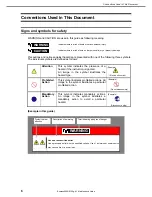
Conventions Used in This Document .................................................................................................................... 6


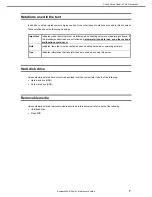
Notations used in the text ................................................................................................................... 7


Hard disk drive .................................................................................................................................... 7


Removable media ............................................................................................................................... 7


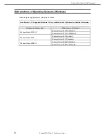
Abbreviations of Operating Systems (Windows) ................................................................................. 8


Trademarks ........................................................................................................................................................... 9


License Notification ............................................................................................................................................. 10


Warnings and Additions to This Document .......................................................................................................... 12


Latest editions ................................................................................................................................... 12


Chapter 1

  Maintenance.................................................................................................................................... 13


1.

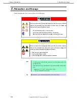
 Relocation and Storage .................................................................................................................................. 14


2.

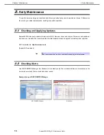
 Daily Maintenance .......................................................................................................................................... 16


2.1

 Checking and Applying Updates ................................................................................................ 16


2.2

 Checking Alerts .......................................................................................................................... 16


2.3

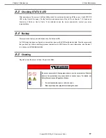
 Checking STATUS LED .............................................................................................................. 17


2.4

 Backup ....................................................................................................................................... 17


2.5

 Cleaning ..................................................................................................................................... 17


2.5.1

 Cleaning the server ......................................................................................................... 18


2.5.2

 Cleaning the tape drive ................................................................................................... 18


2.5.3

 Cleaning the keyboard and mouse .................................................................................. 18


3.

 User Support................................................................................................................................................... 19


3.1

 Maintenance Services ................................................................................................................ 19


3.2

 Before Asking for Repair ............................................................................................................ 19


4.

 Collecting Failure Information ......................................................................................................................... 20


4.1

 Collecting Event Logs ................................................................................................................ 20


4.1.1

 Windows Server 2012 R2 / Windows Server 2012 .......................................................... 20


4.1.2

 Windows Server 2008 R2 ................................................................................................ 22


4.2

 Collecting Configuration Information .......................................................................................... 23


4.2.1

 Windows Server 2012 R2 / Windows Server 2012 .......................................................... 23


4.2.2

 Windows Server 2008 R2 ................................................................................................ 24


4.3

 Collecting User-Mode Process Dump ........................................................................................ 24


4.4

 Collecting Memory Dump ........................................................................................................... 24


5.


Troubleshooting .............................................................................................................................................. 25


5.1


Problem at Powering On ........................................................................................................... 25


5.2


Problem at Starting EXPRESSBUILDER .................................................................................. 26


5.3


Problem of OS Installation ........................................................................................................ 28


5.4


Problem at Starting OS ............................................................................................................. 31


5.5


Problem of Windows STOP Error.............................................................................................. 32


5.6


Problem of RAID System .......................................................................................................... 32


5.7


Problem of Internal Devices and Other Hardware ..................................................................... 34


5.8


Problem of OS Operations ........................................................................................................ 36


5.9


Problem of EXPRESSBUILDER on Windows ........................................................................... 36


5.10


Problem of Bundled Software .................................................................................................. 37


5.11


Problem of Optical Disk Drive .................................................................................................. 38


5.12


Problem at Powering Off .......................................................................................................... 38


6.


Windows System Recovery ............................................................................................................................ 39


6.1


Recovery of Windows Server 2012 R2 / Windows Server 2012 ............................................... 39


Summary of Contents for Express5800/E120g-M

Page 1: ...Express Server Express5800 Series Express5800 E120g M EXP704 EXP705 Maintenance Guide Chapter 1 Maintenance Chapter 2 Useful Features Chapter 3 Appendix 10 113 01 104 02 April 2016 NEC Corporation 20...

Page 2: ...on of peripheral devices and suitable location for this server Chapter 3 Setup System BIOS configurations and summary of EXPRESSBUILDER Chapter 4 Appendix Specifications and other information Installa...

Page 3: ...4 Collecting Failure Information 20 4 1 Collecting Event Logs 20 4 1 1 Windows Server 2012 R2 Windows Server 2012 20 4 1 2 Windows Server 2008 R2 22 4 2 Collecting Configuration Information 23 4 2 1 W...

Page 4: ...2 2 Server Configuration Utility Main Menu 98 2 3 EXPRESSSCOPE Engine 3 99 2 4 Setting BMC Configuration 100 2 4 1 Network 101 2 4 2 User Management 103 2 4 3 Mail Alert 105 2 4 4 SNMP Alert 107 2 4...

Page 5: ...ServerAgentService for Windows 160 8 2 NEC ESMPRO Manager 160 8 3 NEC ESMPRO Agent Extension 160 8 4 Server Configuration Utility 160 8 5 NEC ExpressUpdate Agent 160 9 NEC Product Info Collection Util...

Page 6: ...dicates the presence of a hazard if the instruction is ignored An image in the symbol illustrates the hazard type Prohibited Action This symbol indicates prohibited actions An image in the symbol illu...

Page 7: ...dures described are not followed hardware failure data loss and other serious malfunctions could occur Note Indicates items that must be confirmed when handling hardware or operating software Tips Ind...

Page 8: ...Supported Windows OS in Installation Guide Windows for detailed information Notations in this document Official names of Windows Windows Server 2012 R2 Windows Server 2012 R2 Standard Windows Server...

Page 9: ...nited States and or other countries QLogic is a registered trademark of Qlogic Corporation Broadcom NetXtreme are registered trademarks or trademarks of the Broadcom Corporation in the U S and other c...

Page 10: ...IGHT HOLDERS AND CONTRIBUTORS AS IS AND ANY EXPRESS OR IMPLIED WARRANTIES INCLUDING BUT NOT LIMITED TO THE IMPLIED WARRANTIES OF MERCHANTABILITY AND FITNESS FOR A PARTICULAR PURPOSE ARE DISCLAIMED IN...

Page 11: ...E USE OF THIS SOFTWARE EVEN IF ADVISED OF THE POSSIBILITY OF SUCH DAMAGE This product includes cryptographic software written by Eric Young eay cryptsoft com This product includes software written by...

Page 12: ...document contact your sales representative 5 Regardless of article 4 NEC Corporation assumes no responsibility for effects resulting from your operations 6 The sample values used in this document are...

Page 13: ...ing Failure Information Describes how to collect the failure information See this section in case of a failure 5 Troubleshooting Describes how to troubleshoot the server See this section if you suspec...

Page 14: ...plug before installing or removing the server CAUTION Be sure to observe the following precautions to use the server safely Failure to observe the precautions may cause burns injury and property dama...

Page 15: ...the cables from the server 4 Pack the server securely to protect from damage shock and vibration Important If this server and internal optional devices are suddenly moved from a cold place to a warm p...

Page 16: ...formation for BIOS firmware driver and others of the server and peripheral devices on our website We recommend that the latest update always be applied for stable system operation NEC corporate site h...

Page 17: ...ou periodically back up the data on HDD If a RAID array has been configured on your system back up the RAID configuration data We also recommend that you back up it after a rebuilding process required...

Page 18: ...r lukewarm water and squeeze it firmly 5 Rub off stains on the server with the cloth prepared in step 4 6 Soak a soft cloth in water squeeze it firmly and wipe the server with it once again 7 Wipe the...

Page 19: ...e occurred follow the steps below 1 Check if the power cord and cables to other products are properly connected 2 See Chapter 1 5 Troubleshooting If you find a symptom similar to your problem take the...

Page 20: ...r indicating virtual memory shortage Ignore this message and proceed with starting the system Restarting the system may result in an inability to properly dump the data 4 1 Collecting Event Logs Colle...

Page 21: ...lick Control Panel from Settings 3 Click System and Security View event logs on Control Panel 4 Select the type of log in Windows Logs Application records events related to running applications Securi...

Page 22: ...Windows Server 2008 R2 1 Click Administrative Tool and then click Event Viewer from Control Panel 2 Select the type of log in Windows Logs Application records events related to running applications Se...

Page 23: ...occurs restart the system and then follow the procedure below 4 2 1 Windows Server 2012 R2 Windows Server 2012 1 Click Search on the charm bar You can directly choose Run on the menu that appears whe...

Page 24: ...n Installation Guide Windows 4 4 Collecting Memory Dump If an error occurs the dump file should be saved to acquire necessary information You can specify any location for saving the diagnostic informa...

Page 25: ...ss the power switch on the front of the server to turn on the power the POWER LED ON When power cord is connected the initialization of EXPRESSSCOPE Engine 3 BMC starts During initialization the power...

Page 26: ...Internal Flash Memory during POST After starting the server press F3 key when the following message appears Press F2 Setup F3 Internal Flash Memory F4 ROM Utility F12 Network Have you inserted a CD D...

Page 27: ...les representative Failed to find a file Update Internal Flash Memory by using EXPRESSBUILDER DVD that supports this server Failed to open a file Failed to get the parameters of a file Failed to write...

Page 28: ...sure that the hard disk drive is installed securely and that cables are properly connected Is the disk format correct Follow the table below to create a partition depending on the boot mode Boot mode...

Page 29: ...n of Windows SM Bus Controller PCI Simple Communications Controller Base System Device System Interrupt Controller Performance Counters PCI Device There is no problem with this server Unable to access...

Page 30: ...uter name 15 characters more more Follow the steps below to install the telnet service 1 Adjust the computer name to 14 characters or less 2 Click Run on Start menu 3 Type tlntsvr service in the Open...

Page 31: ...re RAID Configraition Utility or Off line Utility Is the RAID controller found by POST Be sure to connect the RAID controller correctly and retry Is the RAID controller installed firmly straight into...

Page 32: ...the power at the blue screen STOP error screen Perform the forced shutdown continue to press the power switch for at least four seconds to turn off the server 5 6 Problem of RAID System Unable to rebu...

Page 33: ...psed restart the server BBU is failed Displayed when battery is failed Contact your sales representative BBU is discharged Displayed when battery voltage is low Check the cache mode current value abou...

Page 34: ...Embedded MegaRAID system the events of starting Rebuild are not logged on Log Viewer of Universal RAID Utility and system event log When starting Rebuild from Universal RAID Utility on LSI Embedded M...

Page 35: ...ollers appear with different names on Device Manager When N8190 157A 158A 159 160 is used in Windows a different controller name is displayed per controller in Device Manager It is not a problem in op...

Page 36: ...IOS Setup Utility Have you completed protocol and services settings Make sure that the network driver for the server has been installed and the network protocol such as TCP IP or services have been pr...

Page 37: ...d B when creating the repository If the drive letters from C to W are already assigned drive letters cannot be assigned to four temporary drives and the repository cannot be created The following mess...

Page 38: ...f each tab to English US 5 11 Problem of Optical Disk Drive Unable to access or play a CD DVD Is the CD DVD ROM supported by the server CD with copy guard feature is not supported CD DVD for Macintosh...

Page 39: ...nnot recover the Windows system 6 1 Recovery of Windows Server 2012 R2 Windows Server 2012 If the Windows does not start normally you can recover it using the feature of the Windows installation disc...

Page 40: ...essing is in progress when resetting the server 7 2 BMC Reset Press BMC RESET Switch only if a problem occurs in EXPRESSSCOPE Engine 3 BMC Usually do not press this switch To reset the BMC press BMC R...

Page 41: ...does not work Continue to hold POWER Switch of the server for at least four seconds The power is forcibly turned off To turn on the power back again wait at least 30 seconds after turning off the powe...

Page 42: ...lear the password of BIOS Setup Utility SETUP by using the jumper switch Tips Usually use Load Setup Defaults of BIOS Setup Utility SETUP to recover the settings to the factory settings To clear the p...

Page 43: ...Avoid installing under extreme temperature conditions Important Take anti static measures before operating the server For detailed information on static electricity see Chapter 1 1 8 Anti static Measu...

Page 44: ...tional Devices in User s Guide to remove server module 2 Locate the PASSWORD CLEAR jumper by referring the above figure 3 Change the jumper switch from Default to Clear 4 Reassemble the server and tur...

Page 45: ...he server 8 1 Test Items The following items are tested in System Diagnostics Memory CPU cache memory Hard disk drive Important To avoid affecting a network and storage system disconnect a LAN cable F...

Page 46: ...intended for maintenance personnel Diagnostics tool title Shows the name and version of the diagnostic tool Test window title Shows the progress of the diagnostics Test End is displayed when the diagn...

Page 47: ...ws the diagnostics completion screen of the above diagnostics Device List Shows a list of connected devices Log Info Shows the log information of the diagnostics Log information can be saved To save i...

Page 48: ...ver 2 Press F4 key while the message below appears Press F2 SETUP F3 Internal flash memory F4 ROM Utility F12 Network Tips If boot mode is set to legacy BIOS mode Offline Tools is started by pressing...

Page 49: ...s representative if a trouble that requires Off line Maintenance Utility occurs Off line Maintenance Utility has the following features IPMI Information Viewer Displays System Event Log SEL Sensor Dat...

Page 50: ...ote Connect the LAN cable to the connector on management LAN port Or if Shared BMC LAN feature is used connect the LAN cable to the corresponding LAN connector You can also control Offline Tools remot...

Page 51: ...nfiguration Describes the RAID configuration utility installed in the server 6 Details of EXPRESSBUILDER Describes the EXPRESSBUILDER 7 EXPRESSSCOPE Engine 3 Describes EXPRESSSCOPE Engine 3 8 NEC ESMP...

Page 52: ...3 Internal Flash Memory F4 ROM Utility F12 Network a different message may appear depending on the environment If you press F2 SETUP will start after POST and the Main menu appears You can also start...

Page 53: ...I Spec Version Display only Shows the UEFI Spec version that BIOS supports Memory Information Total Memory Display only Shows the total capacity of installed memory System Language English Fran ais Es...

Page 54: ...red Check the system clock monthly Additionally if you implement the server in a system that requires highly accurate time use of a time server an NTP server is recommended If the system time becomes...

Page 55: ...menus that show a to their left select a menu and press the Enter key to display its submenu When UEFI is selected for Boot Mode When Legacy is selected for Boot Mode Note Network Stack Configuration...

Page 56: ...acent Cache Line Prefech Disabled Enabled Set the optimal access from memory to cache to either Enabled or Disabled Execute Disable Bit Disabled Enabled Enable or disable Execute Disable Bit feature T...

Page 57: ...Enterprise Linux 6 x86_64 Windows Server 2012 Windows Server 2012 R2 X2APIC feature must be Disabled when using an OS shown below Red Hat Enterprise Linux 6 x86 Windows Server 2008 Windows Server 200...

Page 58: ...e processor 1 supports Intel 64 architecture Hyper Threading Display only Supported is shown when the processor 1 supports Hyper Threading Technology Processor 2 CPUID Display only Shows the ID or Pro...

Page 59: ...s b Processor Power Management submenu The screen shown below is when Custom is selected for Power Management Policy If any other parameter than Custom is selected for Power Management Policy the para...

Page 60: ...tion C6 Retention No Limit Specify the upper limit for Package C State of processor EIST Disabled Enabled Enable or disable the Enhanced Intel SpeedStep R Technology feature This option is displayed o...

Page 61: ...le the feature that adjusts the operating frequency of Uncore in each processor Uncore Frequency Coordination Disabled Enabled Use this option to adjust uncore frequency between processors This option...

Page 62: ...tomatically selected after DIMMs are reconfigured Memory Frequency Limit Auto 1333 MHz 1600 MHz 1866 MHz 2133 MHz 2400 MHz Specify the upper limit of operating frequency of memory The operating freque...

Page 63: ...l capacity of installed memory Current Memory Speed Display only Shows the current memory operating frequency CPU1_DIMM1 8 Status CPU2_DIMM1 8 Status Display only Shows capacity and status of each DIM...

Page 64: ...porting Onboard VGA is excluded 4GB PCI Hole Granularity 3 GB 2 GB 1 GB Specify the size of address space for PCI device Above 4G Decoding Disabled Enabled Enable or disable the function that maps the...

Page 65: ...LAN Controller Disabled Enabled Enable or disable the onboard LAN controller This option is fixed to Enabled if Shared LAN is enabled in Off line Tools LAN1 Option ROM Scan Disabled Enabled Enable or...

Page 66: ...er Descriptions Target Link Speed Limit Auto 2 5 GT s 5 0 GT s Specify the upper limit of link speed of onboard PCI device and PCI devices connected to each PCI slot PCI 1 2 Slot Link Speed Limit 2 5...

Page 67: ...the upper limit of QPI link speed VT d Disabled Enabled Enable or disable Intel R Virtualization Technology for Directed I O feature Virtualization of I O feature This option is displayed only when t...

Page 68: ...s on the left move the cursor to it and then press the Enter key to show its submenus For details about the options see the table below Option Parameter Descriptions SATA Information SATA Mode Disable...

Page 69: ...a SATA Information submenu For details about the options see the table below Option Parameter Descriptions SATA Port0 Display only Shows a device connected to each port Not Present is shown when no d...

Page 70: ...n Start Unit command is issued to USB mass storage device Controller Timeout 1 sec 5 sec 10 sec 20 sec Specify the timeout period when Control Bulk and Interrupt Transfer commands are issued to USB Co...

Page 71: ...al Port Configuration submenu From the Advanced menu select Serial Port Configuration and then press the Enter key to display the menu screen shown below From BIOS Redirection Port select Serial Port...

Page 72: ...utdown feature of serial port Select Enabled when a device that supports this feature is connected Console Redirection Settings BIOS Redirection Port Disabled Serial Port A Serial Port B Enable or dis...

Page 73: ...ou cannot select Network Stack Configuration submenu if Boot Mode is Legacy To select Network Stack Configuration submenu change Boot Mode to UEFI For details about the options see the table below Opt...

Page 74: ...ter Descriptions iSCSI Initiator Name Alphanumeric character between 4 and 223 Specify the name of iSCSI Initiator Initiator name must be IQN format iSCSI Qualifier Name The menu items below can be se...

Page 75: ...20g M Maintenance Guide 75 Chapter 2 Useful Features 1 Add an Attempt submenu Note MAC address is displayed when onboard LAN controller or UEFI driver for PCI device is loaded Option Parameter Descrip...

Page 76: ...timeout in msec for iSCSI connection OUI format ISID Display only Displays OUI format ISID Configure ISID 6 digit numerics Specify the lower 3 bytes of OUI format ISID MAC address is stored as default...

Page 77: ...ual Specify CHAP type This item is displayed when CHAP is selected for Authentication Type CHAP Name Up to 126 Alphanumeric characters Specify CHAP name This item is displayed when CHAP is selected fo...

Page 78: ...See MAC XX XX XX XX XX XX submenu 3 Delete Attempts submenu Option Parameter Descriptions Attempt XX Disabled Enabled Select Enabled for an iSCSI attempt you want to delete Commit Changes and Exit Sa...

Page 79: ...nge Attempt Order Specify the priority of iSCSI attempt Press the Enter key to open the pop up window and specify the priority by using or key Commit Changes and Exit Save the current setting and retu...

Page 80: ...ls about the options see the table below Option Parameter Descriptions UEFI Driver Name This item is displayed when onboard LAN controller or UEFI driver for PCI device is loaded The on screen menu de...

Page 81: ...he options see the table below Option Parameter Descriptions Create new VLAN VLAN ID 0 4094 Specify VLAN ID Priority 0 7 Specify VLAN Priority Add VLAN Add VLAN Configured VLAN List VLAN ID x Priority...

Page 82: ...alth submenu For details about the options see the table below Option Parameter Descriptions UEFI Driver Name Display only Displays status of UEFI Driver Heaalth This item is displayed when onboard LA...

Page 83: ...gure the settings Select Administrator Password or User Password and then press the Enter key to display the screen where you can register change the password Tips Administrator Password must be set b...

Page 84: ...rd can be set when SETUP is started by administrative right or user right Security Configuration Password On Boot Disabled Enabled Enable or disable the feature that requires a password entry on boot...

Page 85: ...able the Secure Boot function This function is enabled when the key is registered Secure Boot Mode Standard Custom Specify the policy that uses the Secure Boot function in the standard settings Invali...

Page 86: ...You can execute this section only when you set Provision Factory Default keys to Enabled Save All Secure Boot Variables Save all keys and signature databases PK KEK DB DBX and DBT in an external medi...

Page 87: ...e NMI is asserted when PCIe Uncorrectable error is detected and PCI PERR or SERR is detected FRB 2 Policy Retry 3 Times Disable FRB2 Timer Always Reset Specify how the system should operate if FRB lev...

Page 88: ...inues OS booting regardless of user s response even if an error is detected during POST Memory Error Halt Boot Enable or disable the feature to suppress OS booting when POST detects a memory degradati...

Page 89: ...ST execution This parameter is automatically changed to Disabled after the measurement Always The power is measured at every POST execution If the following hardware devices are added replaced specify...

Page 90: ...Number Display only Shows the part number of chassis Chassis Serial Number Display only Shows the serial number of chassis Onboard LAN1 MAC Display only Shows the MAC addoress of onboard LAN1 Onboard...

Page 91: ...45 600 Specify the delay time The minimum configurable time may be changed from factory set value The minimum configurable time is displayed when executing Load Setup Defaults This menu appears when M...

Page 92: ...us before AC power was turned off AC LINK setting Stay Off Last State Power On Operating DC power is ON Off On On Halting DC power is also OFF Off Off On Forced shutdown Off On On Continue pressing th...

Page 93: ...is shown as Unavailable and inaccessible run with Disabled state automatically Bootup Numlock State On Off Enable or disable Numlock feature of keyboard Setup Prompt Timeout 0 65535 Specify the time...

Page 94: ...hen the boot of the device that is the lowest in the Priorities of the same device type has failed a device of the Priorities of the next device type is booted For example if there are 2 Priorities fo...

Page 95: ...Remote CD DVD devices are registered as the device of highest priority in CD DVD Priorities If Load Setup Defaults in the Save Exit menu is executed AMI Remote CD DVD devices are registered as the dev...

Page 96: ...nd Power Off The SETUP utility closes with all the changes saved in NVRAM After the SETUP utility closes the power of the server is automatically turned off d Discard Changes and Power Off The SETUP u...

Page 97: ...If you press the F4 key while the POST is running the Keyboard type selection menu appears Keyboard type selection menu 2 When you select a type of keyboard that is connected to the server the Off li...

Page 98: ...view or set configuration information concerning BMC After you change parameter value for each item select OK to apply the new value to BMC See Chapter 2 2 3 EXPRESSSCOPE Engine 3 for details b ECO Y...

Page 99: ...tion After you change parameter value for each item select OK to apply the new value to BMC See Chapter 2 2 4 Setting BMC Configuration for details b Clear SEL You can erase SEL System Event Log data...

Page 100: ...anagement You can manage users who use BMC See Chapter 2 2 4 2 User Management for details c Mail Alert You can view E mail alert issued from BMC and change parameter setting See Chapter 2 2 4 3 Mail...

Page 101: ...ting by Full Duplex at speed of 10 Mbps 10Mbps Half Connecting by Half Duplex at speed of 10 Mbps Auto Negotiation BMC MAC Address Display MAC Address of BMC DHCP Determine whether to dynamically obta...

Page 102: ...able SSH Port Number Specify the SSH port number 11 22 1 Can be specified if the server supports this feature 2 When set to Shared BMC LAN the BMC LAN port is disabled When set to Shared BMC LAN the s...

Page 103: ...Directory 5 6 Blank Authentication Password Set the authentication password for Active Directory 5 7 Blank User Domain Name Specify the user domain name 5 8 Blank Timeout Specify timeout period for c...

Page 104: ...r other number are not allowed 3 Up to 19 ASCII characters can be used excluding blank quotation ampersand question mark equal sign and 4 Privileges are defined as follows Administrator User who has a...

Page 105: ...le of To 3 1 Disable To 3 E Mail Address Specify the mail address of To 3 2 3 Blank From Specify the mail address of From 3 Blank Reply To Specify the mail address of Reply To 3 Blank Subject Specify...

Page 106: ...st Execute test by sending an alert by mail 10 1 When Mail Alert is enabled at least one address should be enabled 2 Can be specified only when To X is set to Enable 3 Up to 255 characters including a...

Page 107: ...r disable tertiary receiver 4 Disable IP Address3 Specify the IP Address of tertiary receiver 5 0 0 0 0 Alert Level Alert Level Specify the kind of event to alert Error Warning Error When Error is det...

Page 108: ...elect a keyboard language Japanese JP English US French FR German DE English US Remote Media Encryption Enable or disable encryption Enable Remote CD DVD No Encryption Specify the port number of remot...

Page 109: ...cify the Authentication Key 4 5 guest Redirection Enable or disable Redirection feature 4 6 Enable 1 When this item is changed to from Overwrite oldest SEL all log records in the SEL Repository are cl...

Page 110: ...returns to BMC Configuration menu Enter key Clears SEL 2 6 Resetting BMC If you select Reset on EXPRESSSCOPE Engine 3 menu the confirmation message as show below appears Confirmation message BMC Rese...

Page 111: ...mation message as show below appears Confirmation message Initialization ESC key Aborts processing and returns to Main menu Enter key Initializes BMC configuration settings and restores the default va...

Page 112: ...r consumption Watt CPU Throttling Shows Current Maximum Minimum Average CPU throttling rate 2 Memory Throttling Shows Current Maximum Minimum Average memory throttling rate 2 3 Configuration Aggressiv...

Page 113: ...on Performance Optimized Disable CPU Cores Specify the number of cores to be disabled Allowable value is between 0 and Number of maximum cores 1 8 0 1 These values are reference purpose only Each valu...

Page 114: ...s 2 9 Initializing ECO Setting If you select Configuration Initialization on ECO menu the confirmation message as show below appears Confirmation message Initialization ESC key Aborts processing and r...

Page 115: ...e the write protection switch and then connect it again 3 1 Notes on Using Flash FDD Do not use Flash FDD to back up data Flash FDD can be used for a temporary data only 3 1 1 Compensation for recorde...

Page 116: ...C ESMPRO Manager online help 4 1 Supported OS The power control feature is available for the following OSs Windows Server 2008 R2 Standard x64 Windows Server 2008 R2 Enterprise x64 Windows Server 2012...

Page 117: ...ID Configuration Utility 5 1 1 Starting SETUP Turn on the server and wait for POST to proceed After a while the following message appears at the bottom left of the screen Press F2 SETUP F4 ROM Utility...

Page 118: ...menu The Advanced menu appears if you move the cursor to the position of Advanced If you select UEFI Driver Configuration and press the Enter key the following submenu appears Select LSI Software RAID...

Page 119: ...9 Chapter 2 Useful Features 5 1 3 Quitting LSI Software RAID Configuration Utility To quit the utility press the Esc key on the TOP menu of LSI Software RAID Configuration Utility The following screen...

Page 120: ...on UEFI Driver TimeStamp UEFI driver build timestamp Change Controller Properties Change of the parameter for the RAID controller Apply Changes Reflecting the change Set Factory Defaults Setting to th...

Page 121: ...cal Drive The recommended setting is Enabled Read Ahead Enable Read Ahead setting View Associated Drives Displays the HDD configuring the Virtual Drive Select Virtual Drive Operations Virtual Drive op...

Page 122: ...ct Drive Operations Operations of the Physical Drives Select Drive Physical Drive selection Start Locate Device dependent Lights on blinks the LED of the slot on which the selected Physical Drive is m...

Page 123: ...Drive Management and then Create Configuration 3 For Select RAID Level on the following screen select the RAID level RAID0 RAID1 or RAID10 Run LSI Software RAID Configuration Utility Create add Virtu...

Page 124: ...p The procedures to create the virtual drive in each case are following below Note Up to eight virtual drives can be created For RAID10 only creating a new virtual drive is available For RAID10 the vi...

Page 125: ...cal device type is displayed on the following screen select the physical device to be created and select Enabled 4 Select all of the physical devices to be created select Apply Changes and then select...

Page 126: ...Size Unit Specify the unit MB GB TB used for Virtual Drive Size 5 4 Disk WC Specify the Disk Write Cache policy Parameter Remarks Enable Write back Disable Write through Recommended For this server S...

Page 127: ...Chapter 2 Useful Features 6 When all the settings are completed select Save Configuration Note You may select either of the upper or lower Save Configuration which is provided at two locations 7 Selec...

Page 128: ...2 New creation RAID10 1 Select RAID10 for Select RAID Level 2 Select Select Drives under Span1 and then select the device type for Select Media Type Note Do not select Both This platform does not sup...

Page 129: ...lected physical device is displayed select two physical devices to be created and then select Enabled 4 Select all of the physical devices to be created select Apply Changes and then select OK on the...

Page 130: ...pe for Select Media Type 7 When the selected physical device is displayed select two physical devices to be created and then select Enabled 8 Select all of the physical devices to be created select Ap...

Page 131: ...the Read Ahead setting Parameter Remarks Disable Does not perform read ahead Enable Performs read ahead Recommended Note For RAID 10 the virtual drive can be created only with the maximum size Parame...

Page 132: ...pter 2 Useful Features 10 When all of the settings are complete select Save Configuration Note You may select either of the upper or lower Save Configuration which is provided at two locations 11 Sele...

Page 133: ...elect Free Capacity for Select Drives From 2 Select Select Drive Groups 3 Select the Drive Group to be additionally created for Choose Drive Group and then select Enabled 4 Select Apply Changes and th...

Page 134: ...rive Size Specify the capacity of the virtual drive 5 3 Virtual Drive Size Unit Specify the unit MB GB TB used for Virtual Drive Size Important The Disk WC and Read Ahead settings reflect the original...

Page 135: ...ve is created 5 Select Virtual Drive Management and then Manage Virtual Drive Properties and check the Virtual Drive information on the following screen When multiple virtual drives are created for Se...

Page 136: ...lized for Select Virtual Drive Important Data is lost after initialization Take extreme care to select the correct Virtual Drive 8 Select Virtual Drive Operation and then select Fast Initialization on...

Page 137: ...following screen to start the Fast Initialization Note Fast Initialization completes in a few seconds or several tens of seconds 10 Select OK 11 If you are going to install the OS on the created virt...

Page 138: ...Universal RAID Utility User s Guide Important Check Consistency on the LSI Software RAID Configuration Utility takes long time Run Check Consistency from the Universal RAID Utility on the OS Inconsis...

Page 139: ...rom the Universal RAID Utility on the OS If you need to run Rebuild on the LSI Software RAID Configuration Utility follow the procedure below 1 Replace a physical device and then restart the server 2...

Page 140: ...5 Select Drive Operations and then select Rebuild 6 Select Start Operation 7 Select OK to start the rebuild Note The status of Operation Progress is not automatically updated If you want to update the...

Page 141: ...HotSpare 1 Connect a physical device for hot sparing and then turn on the server 2 Run LSI Software RAID Configuration Utility 3 On the TOP menu screen select Drive Management Connect the physical dev...

Page 142: ...5 RAID System Configuration Express5800 E120g M Maintenance Guide 142 Chapter 2 Useful Features 4 Select Select Drive and then select the physical device for hot sparing 5 Select Drive Operation...

Page 143: ...Guide 143 Chapter 2 Useful Features 6 Select Assign Global Hot Spare Drive 7 Select Start Operation and then select OK 8 Return to the TOP menu screen 9 Select Drive Management 10 Select View Global H...

Page 144: ...ce Guide 144 Chapter 2 Useful Features 12 Exit LSI Software RAID Configuration Utility Note To cancel the HotSpare setting select Drive Management Drive Operations Select Drive to select the HotSpare...

Page 145: ...e RAID Configuration Utility takes long time Run Check Consistency from the Universal RAID Utility on the OS For RAID0 running Check Consistency is not required 1 From the TOP menu of LSI Software RAI...

Page 146: ...Configuration Express5800 E120g M Maintenance Guide 146 Chapter 2 Useful Features 2 Select Select Virtual Drive Operations 3 Select the target virtual drive for Select Virtual Drive 4 Select Virtual D...

Page 147: ...5 RAID System Configuration Express5800 E120g M Maintenance Guide 147 Chapter 2 Useful Features 5 Select Check Consistency 6 Select Start Operation 7 Select Yes on the next screen...

Page 148: ...or Virtual Drive Operation changes to Check Consistency on the Select Virtual Drive Operations screen and the progress is displayed at the bottom of the screen Note The status of Operation Progress is...

Page 149: ...2 Place Drive Online Use this feature to forcibly put a physical device in the FAIL status online From the TOP menu select Drive Management and then Select Drive Operations confirm that the target phy...

Page 150: ...Drive Array Disk Array Disk Array Physical Drive Physical Device Physical Device Drive Group Disk Array Disk Array Tips raidcmd is a command provided by Universal RAID Utility For details refer to Un...

Page 151: ...AID Configuration Utility 15 to 100 High 8 to 14 Middle 0 to 7 Low Consistency Check priority Chk Const Rate of LSI Software RAID Configuration Utility 15 to 100 High 8 to 14 Middle 0 to 7 Low Values...

Page 152: ...l Drive Logical Drive Logical Drive Drive Group Disk Array Disk Array Drive Physical Device Physical Device Tips raidcmd is a command provided by Universal RAID Utility For details refer to Universal...

Page 153: ...display levels Universal RAID Utility Item Setting values of Off line Utility Display levels of Universal RAID Utility Rebuild priority 80 to 100 High 31 to 79 Middle 0 to 30 Low Patrol Read priority...

Page 154: ...2 6 2 Menus of EXPRESSBUILDER 1 Boot Selection Menu will appear Windows Application After installing Starter Pack in the server you can run EXPRESSBUILDER as a Windows application Run NEC EXPRESSBUIL...

Page 155: ...wn in 2 Home Menu appears when you choose OS installation or no key is pressed Tool Menu shown in 3 Tool Menu appears when you choose Tool menu Normal mode Usually choose this mode if you want to run...

Page 156: ...stalling Windows choose Manual Selection in the step 1 of Setup b Utilities Runs a utility in EXPRESSBUILDER For details see Chapter 2 6 3 Utilities Provided by EXPRESSBUILDER c Versions Shows the ver...

Page 157: ...ction manuals b Versions Shows the versions of the included software drivers and EXPRESSBUILDER c Integrated Installation Installs several applications or Starter Pack easily If the menu is not run on...

Page 158: ...initializes formats it All data on Internal Flash Memory is deleted b Update Copies the data of EXPRESSBUILDER DVD or other media to Internal Flash Memory The data is overwritten and all previous dat...

Page 159: ...ing the management LAN port to your network enables you to do the following from a remote site through a web browser and SSH client Managing the server Operating KVM keyboard video and mouse from a re...

Page 160: ...this server remotely with NEC ESMPRO Manager connecting this server s BMC For details see NEC ESMPRO Agent Extension Installation Guide in EXPRESSBUILDER 8 4 Server Configuration Utility Server Config...

Page 161: ...server information Product Info for maintenance by using this utility 9 1 Usage Windows Run the stdclct collect exe contained in the installation folder of this utility This utility is usually instal...

Page 162: ...03 179 RAID Controller 2GB RAID 0 1 5 6 N8103 188 RAID Controller RAID 0 1 For information about installing Universal RAID Utility see Universal RAID Utility in Installation Guide Windows See Universa...

Page 163: ...Maintenance Guide 163 Chapter 2 Useful Features 11 Express Report Service Express Report Service HTTPS For details about Express Report Service Express Report Service HTTPS see Express Report Service...

Page 164: ...ice MG Express5800 E120g M Maintenance Guide 164 Chapter 2 Useful Features 12 Express Report Service MG For details about Express Report Service MG see Express Report Service MG Installation Guide Win...

Page 165: ...r messages for errors detected by the power on self test POST 2 List of Windows Event Logs Shows a list of Windows event logs 3 Accessing Data for Electrical Power Temperature and Processor Utilizatio...

Page 166: ...led Press F1 to resume F2 to setup Messages indicating a memory error in this example the message indicates that CPU1_DIMM1 and CPU1_DIMM2 have failed and that DIMM1 has been forcibly started up The n...

Page 167: ...very jumper is set but recovery images is not found Recovery jumper is set but recovery image is not found Contact your sales representative 8800 DXE_NB_ERROR An error was detected during initializati...

Page 168: ...2_DIMM5 An error was detected in CPU2_DIMM5 A012 Memory Error detected in CPU2_DIMM6 An error was detected in CPU2_DIMM6 A013 Memory Error detected in CPU2_DIMM7 An error was detected in CPU2_DIMM7 A0...

Page 169: ...in CPU1_DIMM2 was detected but because all memory is currently disabled this DIMM was forcibly enabled AE83 CPU1_DIMM3 with error is enabled An error in CPU1_DIMM3 was detected but because all memory...

Page 170: ...ot 02 Option ROM expansion in PCI slot 02 failed B022 Serial Port Configuration Overlapped Overlapping serial port configuration was detected Run SETUP select Advanced Serial Port Configuration and sp...

Page 171: ...ge abnormality was detected C040 SROM data read error An error was detected while reading data on SROM C061 1st SMBus device Error detected An error was detected on 1st SM Bus C062 2nd SMBus device Er...

Page 172: ...start the server C11E Communication with BMC was failed in previous boot Communication with BMC was failed in previous boot Turn off the power and unplug the power cord wait for 30 seconds and then re...

Page 173: ...e device after unplugging the power cord of all the modular servers and after waiting for at least 30 seconds C501 Intel R Node Manager is in Recovery Mode Intel Node Manager is in Recovery Mode Unplu...

Page 174: ...s representative Beep code Description Action 1 3 3 1 No memory in the server Failed to detect a memory Make sure that the DIMMs are correctly inserted 1 5 2 1 No processor in the server Failed to det...

Page 175: ...U Starting up BIOS SETUP MENU This is not an error This message will disappear when SETUP operation is completed Waiting for normal temperature A temperature abnormality was detected inside the server...

Page 176: ...ocessor1 Voltage Lower Critical Processor1 Voltage Upper Critical Processor2 Voltage Lower Non Critical Processor2 Voltage Upper Non Critical Processor2 Voltage Lower Critical Processor2 Voltage Upper...

Page 177: ...Power Supply1 Failure detected A power supply unit abnormality occurred Make sure that the power cord is plugged in Power Supply2 Failure detected Processor Missing No CPU is installed Contact your sa...

Page 178: ...ERR occurred Processor2 Internal Error Sensor Failure Detected Abnormality in a sensor was detected SMI timeout A timeout occurred while servicing system management interrupts Soft Power Control Failu...

Page 179: ...ical Contact your sales representative System Rear FAN3 Lower Non Critical System Rear FAN4 Lower Non Critical System Front FAN1 Lower Non Critical System Front FAN2 Lower Non Critical A fan alarm was...

Page 180: ...ed to device Device RaidPort x Any number replaces x While the system is running This event does not affect system operation If this message is logged because OS has succeeded retry process Windows Se...

Page 181: ...bove message is somewhat different At the time of system start up This event is logged in the system when InfiniBand Adapter is connected This event will be recorded when the type of port could not be...

Page 182: ...ng an OS This is logged only when the OS is installed and there is no problem unless the same event logs are continuously logged 7023 Service Control Manager Error The IP Helper service terminated wit...

Page 183: ...logged only when installing an OS and does not occur repeatedly there is no problem in system operation 1015 Microsoft Windows Security SPP Warning Detailed information of HRESULT Returned hr 0xC004F...

Page 184: ...re is no problem in system operation Windows Server 2012 System Log 4 b57nd60a Warning Broadcom NetXtreme Gigabit Ethernet xx The network link is down Check to make sure the network cable is properly...

Page 185: ...ere is no problem for system operation 153 disk Warning The IO operation at the logical block address for disk was retried The on screen message depends on your environment Also though the character s...

Page 186: ...Microsoft Windows Security SPP Error License Activation slui exe failed with the following error code hr 0x80070057 When installing an OS running an OS for the first time Unless the application event...

Page 187: ...tem This event is logged when activating Windows Server 2012 Hyper V but this event does not affect system operation 15350 Microsoft Windows Hyper V VMMS Error VID Virtual Infrastructure Driver is not...

Page 188: ...last adapter has lost link Network connection has been lost When starting system This event is logged at system startup if a team is configured with Intel R PROSet however there is no problem in syst...

Page 189: ...affect system operation 63 Microsoft Windows WMI Warning A provider QLGCWmiProvider has been registered in the Windows Management Instrumentation namespace root interop to use the LocalSystem account...

Page 190: ...ing Windows Server 2008 R2 Go to the following Microsoft website for details http support microsoft com kb 2003968 en us Applications and Services Logs Microsoft Windows Kernel EventTracing Admin 2 Mi...

Page 191: ...e sample file named as Power vbs created by using Visual Basic Script Start Script Option Explicit Prepare for IPMI Driver Dim osvc oclass Dim oinstance oipmi set osvc getobject winmgmts root wmi set...

Page 192: ...set oclass osvc get microsoft_ipmi for each oinstance in osvc instancesof microsoft_ipmi set oipmi oinstance next Get SDR Repository Info Dim oinparams set oinparams oclass methods_ requestresponse in...

Page 193: ...ensorNum Dim outtmp units1 units2 sensortype oinparams networkfunction ha oinparams lun 0 oinparams responderaddress h20 oinparams command h23 oinparams requestdata array rv_ls rv_ms rc_ls rc_ms 20 14...

Page 194: ...sdridstringtype oipmi execmethod_ requestresponse oinparams Dim outsdridstring Dim idlength j idlength outsdridstringtype ResponseData 3 and 31 oinparams networkfunction ha oinparams lun 0 oinparams r...

Page 195: ...WbemScripting Swbemrefresher Set objProcessor objRefresher AddEnum _ objWMIService Win32_PerfFormattedData_PerfOS_Processor objectSet objRefresher Refresh Dim first first true Do For each intProcesso...

Page 196: ...uilt in flash memory that stored EXPRESSBUILDER as standard You can start EXPRESSBUILDER from it without DVD when pressing F3 key during POST NEC ESMPRO Standard software for the server management Thi...

Page 197: ...d Express5800 E120g M Maintenance Guide 197 Chapter 3 Appendix 5 Revision Record Revision Document Number Date Issued Description 10 113 01 104 01 January 2016 Newly created 10 113 01 104 02 April 201...

Page 198: ...20g M Maintenance Guide April 2016 NEC Corporation 7 1 Shiba 5 Chome Minato Ku Tokyo 108 8001 Japan NEC Corporation 2016 The contents of this manual may not be copied or altered without the prior writ...

Reviews: