background image

1. Installing Internal Optional Devices 


Express5800/R120h-2M  User’s Guide 

111


Chapter 2  Preparations 

1.17 


LOM Card 

The server supports LOM Card which is the replaceable onboard network adapter. 

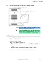
Install LOM Card to the LOM Card slot on motherboard. The motherboard has one slot to install LOM Card. 


Important  You must avoid static electricity to work with the procedure below. For 

details, see Chapter 1 (1.8 Anti-static Measures) in Safety Precautions and 

Regulatory Notices. 


 Installation 

Please prepare the following before installing the option. 


Parts included in the option kit 


T-10 hexalobular driver 


To install the components, follow these steps. 

1. 

See steps 1 to 6 in 

Chapter 2 (1.2 Overview of Installation and Removal)

 for preparations. 

2. 

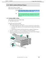
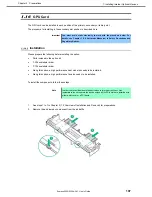
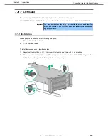
Raise two screw handles at the top of the primary riser card and turn them to the left 180 degrees. Then 

hold both sides of cage and lift them upright to remove the cage. 


Summary of Contents for Express5800/R120h-2M

Page 1: ...s Guide NEC Express Server Express5800 Series Express5800 R120h 2M EXP810 Chapter 1 General Description Chapter 2 Preparations Chapter 3 Setup Chapter 4 Appendix Second edition July 2018 NEC Corporation 2018 ...

Page 2: ...Preparations Installation of additional options connection of peripheral devices and suitable location for this server Chapter 3 Setup System utility configurations and summary of EXPRESSBUILDER Chapter 4 Appendix Specifications and other information Installation Guide Windows Chapter 1 Installing Windows Installation of Windows and drivers and precautions for installation Chapter 2 Installing the...

Page 3: ... 1 Introduction 19 2 Accessories 20 3 Features 21 4 Names and Functions of Parts 25 4 1 Front View With Front Bezel 25 4 2 Front View Without Front Bezel 26 4 3 Rear View 27 4 4 External View 28 4 5 Internal View 29 4 6 Motherboard 30 System Maintenance Switch 31 DIMM slot 32 4 7 Cooling Fan Option 33 4 8 Status Indicators 35 LEDs on the front side of the unit 35 LEDs on the backside of the unit 3...

Page 4: ...upported memory size 70 DIMM installation order 71 Checking DIMM 74 Installation 75 Removal Replacement 76 Memory Function 77 1 12 Riser Card 83 Notes 83 Installing Primary Riser Card 83 Installing Secondary Riser Card 85 Installing Tertiary Riser Card 86 Removal 90 Installing M 2 SATA SSD media 90 Removing M 2 media 91 1 13 PCI board 92 Notes 93 Supported cards and available slots 93 Installing P...

Page 5: ...rive 152 Removing Hot Plug Compatible SATA Hard Disk Drive 154 Installing PCIe SSD Drive 155 Removing the PCIe SSD Drive 156 1 30 Power Supply Unit 157 Installation 157 Replacing a failing power supply unit 159 1 31 Installing Front Bezel 160 2 Installation and Connection 162 2 1 Installation 162 Installing Rack 162 Space and air flow requirements 163 Temperature requirement 164 Power requirements...

Page 6: ...3 3 iLO 5 Network Settings 205 4 EXPRESSBUILDER and Starter Pack 208 4 1 Features of EXPRESSBUILDER Starter Pack 208 4 2 Usage of EXPRESSBUILDER 208 4 3 Usage of Starter Pack 208 5 Installing Software Components 209 6 Turning Off the Server 210 Chapter 4 Appendix 211 1 Specifications 212 2 Glossary 215 3 Revision Record 217 ...

Page 7: ...ymbol indicates the presence of a hazard if the instruction is ignored An image in the symbol illustrates the hazard type Prohibited Action This symbol indicates prohibited actions An image in the symbol illustrates a particular prohibited action Mandatory Action This symbol indicates mandatory actions An image in the symbol illustrates a mandatory action to avoid a particular hazard Example WARNI...

Page 8: ...ot followed hardware failure data loss and other serious malfunctions could occur Note Indicates items that must be confirmed when handling hardware or operating software Tips Indicates information that is helpful to keep in mind when using this server Optical disk drive This server is equipped with one of the following drives These drives are referred to as optical disk drive in this document DVD...

Page 9: ...ide Windows for detailed information Notations in this document Official names of Windows Windows Server 2016 Windows Server 2016 Standard Windows Server 2016 Datacenter Windows Server 2012 R2 Windows Server 2012 R2 Standard Windows Server 2012 R2 Datacenter POST POST described in this manual refers to the following Power On Self Test BMC BMC described in this manual refers to the following Basebo...

Page 10: ...of Microsoft Corporation in the United States and other countries Intel and Xeon are registered trademarks of Intel Corporation of the United States Vmware is a registered trademark or a trademark of Vmware Inc in the United States and other countries All other product brand or trade names used in this publication are the trademarks or registered trademarks of their respective trademark owners ...

Page 11: ...S FOR A PARTICULAR PURPOSE ARE DISCLAIMED IN NO EVENT SHALL THE COPYRIGHT HOLDER OR CONTRIBUTORS BE LIABLE FOR ANY DIRECT INDIRECT INCIDENTAL SPECIAL EXEMPLARY OR CONSEQUENTIAL DAMAGES INCLUDING BUT NOT LIMITED TO PROCUREMENT OF SUBSTITUTE GOODS OR SERVICES LOSS OF USE DATA OR PROFITS OR BUSINESS INTERRUPTION HOWEVER CAUSED AND ON ANY THEORY OF LIABILITY WHETHER IN CONTRACT STRICT LIABILITY OR TOR...

Page 12: ...or the Unified Extensible Firmware Interface UEFI Forum s UEFI Specifications v 2 0 and later together the UEFI Specifications only as necessary to emulate an implementation of the UEFI Specifications and to create firmware applications utilities and or drivers The MIT License Agreement The MIT License Copyright c year copyright holders Permission is hereby granted free of charge to any person obt...

Page 13: ...uct includes software developed by Greg Roelofs and contributors for the book PNG The Definitive Guide published by O Reilly and Associates zlib End User License Agreement zlib License zlib h interface of the zlib general purpose compression library version 1 2 2 October 3rd 2004 Copyright C 1995 2004 Jean loup Gailly and Mark Adler This software is provided as is without any express or implied wa...

Page 14: ...NEC Corporation assumes no responsibility for effects resulting from your operations The sample values used in this document are not actual values Keep this document for future use Latest editions This document was created based on the information available at the time of its creation The screen images messages and procedures are subject to change without notice Substitute as appropriate when cont...

Page 15: ...ing label Warning label are attached on or near the components with potential hazards This label is either attached or printed on the component Do not remove or black out this label and keep it clean If no label is attached or printed on the server contact your sales representative ...

Page 16: ...oltage drop may occur due to lightning strike To prevent this use of UPS is recommended In the following cases check and adjust the system clock before operation After transportation After storage After the server is used following a period of disuse in which storage conditions did not conform to those that guarantee server operations temperature 10 to 35 C humidity 8 to 90 Check the system clock ...

Page 17: ...een from reflecting bright lights and to make the display contents easy to see Working without adjusting the display to a comfortable angle makes it difficult for you to maintain a proper posture and you will get tired easily Adjust the viewing angle before use Adjust the brightness and contrast of the display Display screens have functions to control brightness and contrast The most suitable brig...

Page 18: ...s chapter introduces the features of this server and the name of each part 1 Introduction 2 Accessories Describes the accessories of the server 3 Features Describes the features of the server and the server management 4 Names and Functions of Parts Describes the name of each part contained in this server ...

Page 19: ...he latest microprocessor Intel Xeon processor With our latest technology and architecture we offer high performance and high reliability that could not be accomplished by conventional servers Furthermore with its design for extensibility our servers can be widely used for general purpose For proper use of the unit read this manual carefully to fully understand handling of the product ...

Page 20: ...ached to Front Bezel Safety Precautions and Regulatory Notices Getting Started In addition to these enclosed items the following extra items may be required Operating system or application software Hardware options Drivers Hexalobular Standard etc Check whether all parts are present and complete If some parts are missing or damaged contact the applicable vendor Important The chassis serial number ...

Page 21: ...26 Processor 2 60 GHz 12C 24T 19 25MB TDP 125W Xeon Gold 6128 Processor 3 40 GHz 6C 12T 19 25MB TDP 115W Xeon Gold 6130 Processor 2 10 GHz 16C 32T 22MB TDP 125W Xeon Gold 6132 Processor 2 60 GHz 14C 28T 19 25MB TDP 140W Xeon Gold 6134 Processor 3 20 GHz 8C 16T 24 75MB TDP 130W Xeon Gold 6136 Processor 3 GHz 12C 24T 24 75MB TDP 150W Xeon Gold 6138 Processor 2GHz 20C 40T 27 50MB TDP 125W Xeon Gold 6...

Page 22: ...Hz 28C 56T 38 50MB TDP 205W Turbo Boost Technology feature 1 Hyper Threading Technology feature 1 Intel AVX 512 Extended Instruction Set 2 Intel Ultra Path Interconnect UPI 3 Intel Run Sure Technology 4 High speed memory access DDR4 2133 2400 2666 supported 5 High speed disk access SATA 6Gb s SAS 12Gb s supported High speed 10GBASE SFP 10GBASE T 1000BASE T 100BASE TX 10BASE T interface 10Gbps 1Gbp...

Page 23: ...8 lanes 8 slots Full height 10 PCI Express 3 0 x8 lanes 1 slot dedicated to RAID controller PCI Express 3 0 x8 lanes 1 slot dedicated to LOM card Large capacity memory of up to 3 0TB 6 Can upgrade to multi processor system with up to two processors Expansion Bay for hard disk drives up to 30 slots Optical disk drive bay provided as standard 8x 3 5 inch drive model USB3 0 interface Front 1 port rea...

Page 24: ...ry depending on the type or the number of boards of processor or memory installed 6 For 2 CPU configuration Up to 1 5TB for 1 CPU configuration Maximum available memory capacity depends on the type of processor see below CPU Maximum memory capacity per CPU Processor containing an M in the model Xeon Platinum 8160M 8170M 8176M 8180M Xeon Gold 6134M 6140M 6142M 1 5TB others 768GB 7 Power supply unit...

Page 25: ...mes and Functions of Parts This section describes the names of the server parts 4 1 Front View With Front Bezel 1 Front Bezel A cover for protecting the front of the server This cover can be locked with the provided Bezel Lock Key 2 Key Slot A slot for Bezel Lock Key that is used to lock Front Bezel 1 2 ...

Page 26: ...are remote management of iLO or firmware update the UID LED lights up or flashes if iLO is restarted via UID switch 5 iLO service port USB connector A USB connector used for connecting to iLO such as for acquiring log For details refer to iLO 5 User s Guide 6 USB3 0 connector front Connectors for connecting USB 3 0 interface devices 7 Pull out Tab A tab for showing the model number and serial numb...

Page 27: ...r showing the status of LAN See page 39 10 LAN connectors 1 Connectors for connecting to a network 1000BASE T 100BASE TX 10BASE T 10 1 LAN1 connector 10 2 LAN2 connector 10 3 LAN3 connector 10 4 LAN4 connector 11 ACT LED LEDs for showing the transfer speed of LAN ports See page 39 12 Management LAN Connector A LAN connector which supports 1000BASE T 100BASE TX 10BASE T Incompatible as LANs for reg...

Page 28: ...4 Names and Functions of Parts Express5800 R120h 2M User s Guide 28 Chapter 1 General Description 4 4 External View 1 Top cover 2 Hood latch 1 2 ...

Page 29: ...lled under the heat sink 1 CPU1 required option 2 CPU2 option 4 DIMM option 5 Slot for RAID Controller 6 Motherboard 7 Primary Riser Card Standard riser is standard installed Changeable by option 8 Secondary Riser Card connector Riser card cage are optional 9 Tertiary Riser Card connector Riser card cage are optional 10 Power Supply Unit The numbers after the parenthesized numbers indicate slot nu...

Page 30: ...for optical disk drive 12 Power supply SW USB 3 0 connector 13 Battery connector for RAID controller 14 Power Connector for Expander Board 15 Power Connector for Expander Board 16 Power connector for HDD BP 17 Internal x 2 USB 3 0 connector 18 Connector dedicated to RAID controller Type a 19 Connector for secondary Riser Card CPU2 is required for using the secondary riser card 20 Connector for ter...

Page 31: ...10 Off Reserved SW11 Off Reserved SW12 Off Reserved Important Do not change the system maintenance switch that says Reserved unless it is instructed by the document It may cause the trouble or malfunction of the device 1 Set the SW1 to ON when all the passwords of iLO5 to which administrator authority is given have become unknown or when enabling the iLO5 features 2 Regarding the operation procedu...

Page 32: ...4 Names and Functions of Parts Express5800 R120h 2M User s Guide 32 Chapter 1 General Description DIMM slot DIMM slots are numbered in order 1 to 12 for the processor 2 slot channel Front ...

Page 33: ...ecessary fans installed and running The following displays the structure for installing cooling fans Configuration Fan bay 1 Fan bay 2 Fan bay 3 Fan bay 4 Fan bay 5 Fan bay 6 1xCPU Blank cover Blank cover Fan Fan Fan Fan 2xCPU Fan Fan Fan Fan Fan Fan Containing CPU x 1 and 2 5 inch drive x 24 or 3 5 inch drive x 12 Employing a powerful fan Fan Fan Fan Fan Fan Fan For single processor configuration...

Page 34: ...fan the fan revolves at the minimum speed The server shuts down in the following situations relating to temperature In case a temperature at a cautious level is detected iLO5 executes the shutdown of OS safely In case a temperature at a critical level is detected iLO5 executes not a shutdown but a hard shutdown of OS With Thermal Shutdown function set to Disabled at BIOS Platform Configuration RBS...

Page 35: ...d 2 3 LINK ACT LED 1 Lights in green Linked to the network Flashes in green once per second The network is working Lights off The network is not working 4 UID Switch LED 1 Lights in blue Working in operation Flashes in blue once per second Remote management or firmware upgrade is in progress Flashes in blue 4 times per second The iLO restart sequence using the UID switch has been launched Flashes ...

Page 36: ... amber The function of the system is deteriorating Flashes in red once per second The system is in a critical state 3 3 LINK ACT LED 1 Lights in green Linked to the network Flashes in green once per second The network is working Lights off The network is not working 4 POWER Switch LED 1 Lights in green The system is powered on Flashes in green once per second The power on sequence in progress Ligh...

Page 37: ... applied on all servers Subsystem LED status Motherboard Flashes once Processor Flashes twice Memory Flashes 3 times Riser card board PCIe slot Flashes 4 times LOM card Flashes 5 times RAID controller SAScontroller Flashes 6 times Motherboard PCIe slot Flashes 7 times Power backplane or storage backplane Flashes 8 times Power Supply Unit Flashes 9 times When the STATUS LED on the front panel light...

Page 38: ...y installed Amber Green One cooling fan has failed or has been removed Red Green Two or more cooling fans have failed or have been removed Red Amber One or more of the following conditions may be occurring Only one power supply unit is installed and is in the standby state Power supply failure System board failure Amber Green One or more of the following conditions may be occurring While redundant...

Page 39: ...ts in green Working in operation Flashes in green Working in operation Lights off Not working 4 left AC POWER2 LED Lights in green Normal state Lights off One or more of the following situations are occurring AC power is not supplied Power supply unit has failed Power supply unit is in standby mode Power supply unit exceeds the current limit 4 right AC POWER1 LED Lights in green Normal state Light...

Page 40: ...LED Lights in green A drive is a member of one or more logical drives Flashes in green Rebuilding the drive migrating RAID on the drive migrating or expanding the capacity of the strip size expanding the capacity of the logical drive or erasing the drive Flashes in amber green A drive is a member of one or more logical drives and a drive failure is predicted Flashes in amber Drive is not configure...

Page 41: ...SD drive before completion of the device signal and traffic flow may result in data loss No Item Status Description 1 Release lever 2 DISK ACT LED Rotates in green Drive is working Lights off Drive is not working 3 Remove Protect Switch LED Lights in white Do not remove the drive Removing a drive causes one or more logical drives to fail Flashes in white Hot plug processing Lights off Even if the ...

Page 42: ...5800 R120h 2M User s Guide 42 Chapter 1 General Description 4 9 Identification of Drive Boxes Front BOX Chart number BOX number 1 BOX1 2 BOX2 3 BOX3 Rear BOX Chart number BOX number 1 BOX4 2 BOX5 3 BOX6 Chart number BOX number 1 BOX4 2 BOX6 ...

Page 43: ...4 Names and Functions of Parts Express5800 R120h 2M User s Guide 43 Chapter 1 General Description Mid BOX Chart number BOX number 1 BOX7 ...

Page 44: ...oller Controller Connection to a on board SATA port Connection to a PCI board AROC Type a to be installed on a dedicated connector for RAID controller Connection to a RAID controller PCI board Type p to be installed on riser card Drive bay numbers when a RAID controller is used If the drive back plane is directly connected to the controller the drive bay number starts from 1 Here we illustrate the...

Page 45: ...rations This chapter describes preparations for using this server 1 Installing Internal Optional Devices You can skip this section if you did not purchase any optional devices 2 Installation and Connection Place the server in a suitable location and connect cables following this section ...

Page 46: ...d safely WARNING Be sure to observe the following precautions to use the server safety Failure to observe the precautions may cause death or serious injury For details see Safety Precautions and Regulatory Notices Do not disassemble repair or modify the server Do not remove the lithium battery NiMH battery or Li ion battery Disconnect the power plug when installing and removing devices CAUTION Be ...

Page 47: ...Beware of high temperatures Do not get your fingers caught when installing components If the server is mounted on a rack use the UID switch to identify the target server See Chapter 2 1 3 Installing Internal Optional Devices Remove Front Bezel See Chapter 2 1 4 Removing Front Bezel Trun off the server See Chapter 3 6 Turning Off the Server Disconnect the power cord from the outlet and the server I...

Page 48: ...in the RAID System Attach the air baffle See Chapter 2 1 27 Attaching the air baffle Attach Top Cover See Chapter 2 1 28 Installing Top Cover Mount the server onto the rack See Chapter 2 2 1 Installation Install disk drives See Chapter 2 1 29 Drives Install power supply units See Chapter 2 1 30 Power Supply Unit Attach Front Bezel See Chapter 2 1 31 Installing Front Bezel Installation and removal ...

Page 49: ...ntify the target server When the server is working be sure to identify the target server by using UID Switch first before you turn off the server or disconnect a cable from the server To turn UID LED on press UID Switch When it is pressed again the LED will be off UID switch UID LED UID switch UID LED Front 8x 3 5 inch drive model Front 12x 3 5 inch drive model UID LED Rear ...

Page 50: ...right and unlock the lever seen on the left when you face the front bezel and pull only the left side of bezel by about 10 cm toward you Then as shown in the diagram pull the bezel to the left forward direction with the lock on the left unlocked to remove the bezel from the device Note Be careful not to press the POWER Switch Important If you fail to remove the front bezel properly the front bezel...

Page 51: ...alobular driver T 10 or flathead driver See steps 1 to 5 in Chapter 2 1 2 Overview of Installation and Removal for preparations Unscrew the security screw with the hexalobular driver or flathead driver Unlock the hood latch on the top by pressing from behind and raise the hood latch Slide the cover a little bit to the rear side of the chassis Lift Top Cover and remove it from the server Close Open...

Page 52: ...time with the top cover air baffle expansion slot cover or the blank cover removed If the server operates under these conditions it will not be properly ventilated and the cooling mechanism will not properly function which may lead to damages due to high temperature When installing or removing internal optional devices or when changing the internal cable connection remove the air baffle See steps ...

Page 53: ... not remove the installed TPM Once the TPM is installed it becomes a permanent part of Motherboard During hardware installation or replacement our service counter cannot to enable TPM or encryption technology For security reasons please enable yourself When returning Motherboard for service replacement do not remove the TPM from Motherboard When requested our service provides a TPM with the spare ...

Page 54: ... internal circuitry remain active until AC power is removed Important The surface becomes hot after use so to avoid burns please allow the drive and internal parts of the system to cool before touching To install the components follow these steps 1 Update System Utility Please download the latest version from our support center website For updating System utility please follow the instructions on ...

Page 55: ... device the data including the key stored in TPM are deleted when the power is turned on The TPM that has been removed from the original server and installed on another server 5 Installing the TPM cover 1 Align the holes and locking latches on both sides of the TPM connector 2 Press down the center of the cover firm and straight until you hear a locking sound 6 Re attach the options and cables tha...

Page 56: ...d saved the server prompts for reboot request Press the Enter key to confirm reboot If the following actions were performed the server reboots a second time without user input During this reboot the TPM setting becomes effective Changing TPM bus from FIFO to CRB Enabling or disabling TPM Clearing the TPM 8 Enable TPM functionality in the OS such as Microsoft Windows BitLocker or measured boot For ...

Page 57: ...er 1 1 8 Anti static Measures in Safety Precautions and Regulatory Notices Make sure to use the CPU authorized by NEC Installing a third party CPU may cause a failure of the CPU as well as the motherboard Repair of the server due to failures or damage resulted from installing such a CPU will be charged Update the system ROM before installing the processor if a higher speed processor is to be insta...

Page 58: ...r of logical processors is as shown below Windows Server 2012 R2 320 Windows Server 2016 512 Installation Please prepare the following before installing the option Parts included in the optional processor heat sink kit T 30 hexalobular driver To install the components follow these steps 1 See steps 1 to 7 in Chapter 2 1 2 Overview of Installation and Removal for preparations 2 For the 3 5 inch dri...

Page 59: ...n each heatsink nut in the order indicated on the heatsink label 1 2 3 4 until it no longer turns 4 If installing a second processor install fans in bays 1 and 2 These fans are provided with the processor option kit 5 Make sure that the heat sink is installed on a level with the motherboard Note If the heat sink is not level remove it and then install it again The following probably causes the hea...

Page 60: ...nstall an additional fan unit provided with additional CPU kit Remove the fan blank cover from the fan bay 7 Attach the fan to bay 1 and 2 Fan connection conditions are shown in the table below Fan bay Configuration 1 2 3 4 5 6 1xCPU Blank cover Blank cover Fan Fan Fan Fan 2xCPU Fan Fan Fan Fan Fan Fan ...

Page 61: ...the POST To view this information and additional processor specifications follow the directions below 1 Reboot the server The server restarts and the POST screen is displayed 2 Press F9 key System Utility screen appears 3 Select System Information Processor Information More information about the processors installed on the server appears on the screen 4 Keep pressing ESC key until the main menu is...

Page 62: ...hese conditions poorly controlled airflow and cooling will make it to overheat and cause damage Note In order to prevent the damage to electronic components please start to install the system after conducting the appropriate anti static treatment There is a possibility of causing electrostatic discharge if appropriate grounding wire treatment is not conducted To install the components follow these...

Page 63: ... top cover of the server Note In order to prevent damage of the system due to improper cooling or elevated temperature please do not activate the server or enclosure without implementing any of component or blank on all of drive bays and device bays 7 Please see Chapter 2 2 Installing Internal Optional Devices in this manual to conduct installation and connection and turn the power supply ON Remov...

Page 64: ...ired for redundancy If the cooling fan fails or lacks the redundancy will fail High performance fans may be necessary in 24 x 2 5 inch configuration and 12 x 3 5 inch configuration for the following devices Installing optional GPU riser This device monitors the temperature inside the server controls the cooling fan and cools down the server to the proper temperature The server will undergo a norma...

Page 65: ...r heat sink kit T 30 hexalobular driver 1 4 flat blade screwdriver or nonconductive tool To install the components follow these steps 1 Please follow the cautions below Note The processor assembly must be removed and replaced as a unit Do not remove the processor from the carrier When handling the heatsink always hold it along the top and bottom of the fins Holding it from the sides can damage the...

Page 66: ...3 4 Note Contacts on the motherboard are very fragile and easily damaged To avoid damage to the motherboard do not touch the processor or processor socket contact 3 Lift the processor heat sink module up and remove 4 Turn over the heat sink module and position the contact surface of the processor at the top 5 Install the protective cover on the processor socket 5 Remove the processor from the heat...

Page 67: ... corners of the processor assembly 5 Separate the processor assembly from the heatsink The processor remains attached to the carrier 6 Using alcohol remove thermal grease adhering to the processor Before new thermal grease adheres dry the alcohol Note Do not touch the point of contact of the processor 7 Remove the dust cover of the high performance heat sink 8 Align the pin mark 1 on the processor...

Page 68: ...ndicator on the processor carrier and the socket Align the processor heatsink assembly with the heatsink alignment pins and gently lower it down until it sits evenly on the socket The heatsink alignment pins are keyed The processor heatsink assembly will only install one way Using a T 30 hexalobular screwdriver fully tighten each heatsink nut until it no longer turns Note Be sure to tighten each h...

Page 69: ...nual to conduct installation and connection and turn the power supply ON Identifying processor type The type of processor installed on the server is displayed simply on the POST To view this information and additional processor specifications follow the directions below 1 Reboot the server The server restarts and the POST screen is displayed 2 Press F9 key System utility screen appears 3 Select Sy...

Page 70: ...reason you can provide higher system capacity and bandwidth by installing larger capacity DIMM For the information corresponding to all the types all the types are referred to as DIMM If you specify LRDIMM or RDIMM the information is applicable only to the type It is necessary that the type of all of the memory installed on the server is the same Important This server does not support mix of LRDIM...

Page 71: ...lots Slot number shows DIMM slot ID for spare replacement Please see the following chart for the location of the slot number 2 slot channel Front The order of installation may be different on x1CPU PROC1 configuration and x2 CPU PROC1 PROC2 configuration When only CPU1 is mounted Mounted number CPU1 slot number 1 DIMM 8 2 DIMM 8 10 3 DIMM 8 10 12 4 DIMM 3 5 8 10 5 DIMM 3 5 8 10 12 6 DIMM 1 3 5 8 1...

Page 72: ... 5 7 8 9 10 11 12 19 DIMM 1 3 5 7 8 9 10 11 12 1 3 4 5 6 7 8 9 10 12 20 DIMM 1 3 4 5 6 7 8 9 10 12 1 3 4 5 6 7 8 9 10 12 21 DIMM 1 3 4 5 6 7 8 9 10 12 1 3 4 5 6 7 8 9 10 11 12 22 DIMM 1 3 4 5 6 7 8 9 10 11 12 1 3 4 5 6 7 8 9 10 11 12 23 DIMM 1 3 4 5 6 7 8 9 10 11 12 1 2 3 4 5 6 7 8 9 10 11 12 24 DIMM 1 2 3 4 5 6 7 8 9 10 11 12 1 2 3 4 5 6 7 8 9 10 11 12 Depends on the combination of DIMM DIMM expa...

Page 73: ...d 5122 processor 2400MHz Xeon Silver 4100 Series Xeon Bronze 3100 Series 2133MHz The operation memory speed is decided by rating DIMM speed DIMM attached on each channel processor model and speed selected on System Utility The maximum memory capacity Maximum memory capacity depends on DIMM capacity the number of installed DIMM memory type and the number of processors installed The maximum memory c...

Page 74: ...iption Meaning 1 Capacity 8GB 16GB 32GB 64GB 128GB 2 Rank 1R Single rank 2R Dual rank 4R Quad rank 8R Octal rank 3 DRAM data width X4 4 bit X8 8 bit X16 16 bit 4 Memory generation DDR4 5 The maximum speed of the memory 2133 MT s 2400 MT s 2666 MT s 6 CAS latency P CAS 15 15 15 T CAS 17 17 17 U CAS 20 18 18 V CAS 19 19 19 for RDIMM LRDIMM V CAS 22 19 19 for 3DS TSVLRDIMM 7 DIMM type R RDIMM with re...

Page 75: ...y closes Important Make sure the orientation of the DIMM The DIMM has a notch preventing being incorrectly inserted Do not apply too much pressure when you push a DIMM into the slot Doing so can damage the socket or terminal part Continue to install remove the internal options See Chapter 2 1 27 Attaching the air baffle to attach the air baffle Refer to Chapter 2 1 28 Installing Top Cover in this ...

Page 76: ...ding the trouble shooting on a malfunctioning DIMM or the information on LEDs see 3 Combined LED descriptions Removal Replacement To replace or remove DIMM follow these steps To remove DIMM reverse the installation procedure Be sure to install dummy cover to the slots from where DIMMs are removed Note When removing a defective DIMM check error messages displayed at POST or NEC ESMPRO and check the...

Page 77: ...y function ADDDC Single Device Data Correction SDDC is afunction to restore the data automatically in case one of memory chips stored on DIMM breaks The motherboard of this device has six systems of Memory Channel which controls memory Memory Mirroring Function and Memory Sparing Function are functions to retain redundancy by monitoring of memories and switching among channels Memory Controller 1 ...

Page 78: ...e operating system The followings are the conditions to use this function Install 12 DIMMs per CPU Use DIMMs with the same product number for the device Change the following parameters and save them From system utility set System Configuration BIOS Platform Configuration RBSU System Options Memory Operations Advanced Memory Protection to Mirrored Memory with Advanced ECC Support After rebooting co...

Page 79: ...rocessor Notes for the setting of memory mirroring Even if Mirrored Memory with Advanced ECC Support is set in Advanced Memory Protection and Memory Mirroring Configuration is selected in case DIMM configuration that cannot constitute memory mirroring due to expansion or removal of DIMM is detected Advanced Memory Protection operates as Advanced ECC configuration In this case Advanced ECC is displ...

Page 80: ...lly installed is recognized it changes depending on the number of DIMM installed and the capacity per one For the physical memory capacity available from the operating system refer to the table below The number of CPU The number of memory Types of on board memory 8GB SR 8GB DR 16GB SR 16GB DR 32GB DR 64GB QR 128GB OR 1 8 32GB 48GB 64GB 96GB 192GB 448GB 768GB 12 48GB 72GB 96GB 144GB 288GB 672GB 115...

Page 81: ...elect memory sparing configuration in case DIMM configuration which cannot constitute memory sparing due to expansion or removal of DIMM is detected Advanced Memory Protection operates as Advanced ECC In this case Advanced ECC is displayed in POST s Advanced Memory Protection Mode IML also records the relevant error events Notes for replacements at failure At the time of failure identify damaged D...

Page 82: ...alled in this server Cautions for setting the fault tolerant memory ADDDC If the DIMM configuration that cannot allow the fault tolerant ADDDC configuration is detected while Fault Tolerant Memory ADDDC is set to Advanced Memory Protection and the fault tolerant ADDDC configuration is specified the Advanced ECC setting is enabled when Advanced Memory Protection runs In this case Advanced ECC appea...

Page 83: ...talling or removing a riser card Do not touch the terminals of the riser cards and the leads of electronic components with your bare hand Fingerprints and dust left on them cause the server to malfunction due to a connection failure or damage to the leads Available type of PCI card depends on the type of a riser card Make sure the card type before connecting it to riser card Installing Primary Ris...

Page 84: ...e top of riser card turn the screws to the right 180 degrees while pressing them down Then after fixing the riser card put down the screw handles as before 4 See Chapter 2 1 28 Installing Top Cover to attach the top cover of the server Note In order to prevent damage of the system due to improper cooling or elevated temperature please do not activate the server or enclosure without implementing an...

Page 85: ...obular driver Note In order to prevent the damage to server s main body or the expansion board please remove all the AC power cables before removing installing riser card To install the components follow these steps 1 See steps 1 to 6 in Chapter 2 1 2 Overview of Installation and Removal for preparations 2 Unfasten two screws securing the rear blank cover and pull up the blank cover to remove it N...

Page 86: ...of the system due to improper cooling or elevated temperature please do not activate the server or enclosure without implementing any of component or blank on all of drive bays and device bays 5 Please see Chapter 2 2 Installation and Connection in this manual to conduct installation and connection and turn the power supply ON Installing Tertiary Riser Card Please prepare the following before inst...

Page 87: ...is attached raise the screw handles at the top of riser card turn them to the left 180 degrees and then pull up the riser card to remove the riser card 3 Unfasten 3 screws and remove secondary riser card 4 Attach the secondary riser card removed in step 3 to secondary side of tertiary riser card butterfly riser card and fasten with 3 screws After that proceed to step 6 ...

Page 88: ...ions 5 Remove the 2 screws that fix the secondary riser blank cover in place and remove the cover by lifting it up Note Keep each removed blank covers 6 Remove the 3 screws that fix the tertiary riser blank cover in place and remove the cover by lifting it up Note Keep each removed blank covers ...

Page 89: ...r part of the riser card and push it downwards while turning it 180 to the right to fix the riser card in place Then return the screw handles to their original positions 9 See Chapter 2 1 28 Installing Top Cover to attach the top cover of the server Note In order to prevent damage of the system due to improper cooling or elevated temperature please do not activate the server without implementing a...

Page 90: ...conducting the appropriate anti static treatment There is a possibility of causing electrostatic discharge if appropriate grounding wire treatment is not conducted Please prepare the following before installing the options Parts included in the option kit Phillips screwdriver To install the components follow these steps 1 See steps 1 to 6 in Chapter 2 1 2 Overview of Installation and Removal for p...

Page 91: ...ht 180 degrees while pressing them down Then after fixing the riser card put down the screw handles as before 6 See Chapter 2 1 28 Installing Top Cover to attach the top cover of the server Note In order to prevent damage of the system due to improper cooling or elevated temperature please do not activate the server or enclosure without implementing any of component or blank on all of drive bays a...

Page 92: ... the expansion board please remove all the AC power cables before removing installing riser card All slots support full height PCI cards Use the PCI card length according to the table below Primary riser connector Slot PCIe type 3 slots riser 2 slots riser 1 Full length Full height FL FH PCIe3 x16 8 4 2 1 2 Half length Full height HL FH PCIe3 x16 8 4 2 1 PCIe3 x16 16 8 4 2 1 3 Half length Full hei...

Page 93: ...8 x16 x8 x16 x8 x16 x8 x16 x8 Slot size Dedic ated to RAID Dedic ated to LOM FH FH FH FH FH FH FH FH FH FH FH FH FH FH FH Available size FL FL HL HL HL HL FL FL HL HL HL HL FL FL HL N8103 189 RAID Controller 0MB RAID 0 1 PCI Express 3 0 x8 N8103 190 RAID Controller 2GB RAID 0 1 5 6 PCI Express 3 0 x8 Maximum of up to 1 battery per device N8103 191 RAID Controller 4GB RAID 0 1 5 6 PCI Express 3 0 x...

Page 94: ...with N8190 165 166 N8190 165 Fibre Channel Controller 1ch PCI Express 3 0 x8 1 3 5 2 4 6 7 8 Can t mix with N8190 163 164 171 172 N8190 166 Fibre Channel Controller 2ch PCI Express 3 0 x8 1 3 5 2 4 6 7 8 Can t mix with N8190 163 164 171 172 N8190 171 Fibre Channel controller 1ch PCI Express 3 0 x8 1 3 5 2 4 6 7 8 Can t mix with N8190 165 166 N8190 172 Fibre Channel controller 2ch PCI Express 3 0 x...

Page 95: ...nnector 3 GPU power connecto r N8116 56 x16 x16 FH FL x16 x16 FH HL N8116 58 x16 x16 FH HL x16 x16 FH HL N8116 62 x8 x8 FH FL x16 x16 FH HL x8 x8 FH HL Supporte d N8116 67 x16 x16 FH HL x16 x16 FH HL Supporte d N8116 79 x8 x8 FH FL x8 x8 FH HL x8 x8 FH HL N8116 80 8xPCIe SSD Riser 4 N8154 98 Rear 2 5 inch Drive Cage x16 x16 FH HL 3rd riser card PCIe3 0 Optional Part number SLOT7 SLOT8 Others Slot ...

Page 96: ...mpletely by the power button on the front panel Until the AC power cord is unplugged the power supply circuit is still active in some parts of the machine Note When running a server always ensure proper cooling by attaching the top cover baffle expansion slot cover and blank If the server supports components with hot plug support minimize the amount of time the top cover is open Please prepare the...

Page 97: ...tric parts installed on the board Installing boards with dirt or oil can cause malfunction Note Make sure that the edge of a PCI card bracket is seated into the fixed slot of the riser card unit Depending on type of PCI cards the terminal part of the PCI card may be too large to fit in the connector If you have trouble installing the card remove the card once and try again If you apply excessive p...

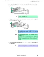
Page 98: ...ht 180 degrees to fix the cage Then put down the screw handle as before 7 See Chapter 2 1 28 Installing Top Cover to attach the top cover of the server Note In order to prevent damage of the system due to improper cooling or elevated temperature please do not activate the server or enclosure without implementing any of component or blank on all of drive bays and device bays 8 Please see Chapter 2 ...

Page 99: ...e machine Note When running a server always ensure proper cooling by attaching the top cover baffle expansion slot cover and blank If the server supports components with hot plug support minimize the amount of time the top cover is open Please prepare the following before installing the options Parts included in the option kit To install the components follow these steps 1 Back up all data in the ...

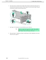
Page 100: ...tor on motherboard with cable connect a cable to PCI card before installing riser card unit 7 Fit the terminal of riser card to the slot on the mother board and insert the terminal firmly into the slot Then fix the riser card Next raise the screw handle at the top of cage and turn the handle to the right 180 degrees to fix the cage Then put down the screw handle as before 8 See Chapter 2 1 28 Inst...

Page 101: ...atment is not conducted Installing RAID Controller Please prepare the following before installing the option Parts included in the option kit To install the components follow these steps 1 Make sure that the following requirements are met The RAID controller battery must be installed in a controller with the FBWC function N8103 196 201 If connecting a cable make sure to connect to a component conn...

Page 102: ... card to direction 1 and remove the blank cover by pulling it out to direction 2 Note Keep each removed blank covers 5 Fit properly the terminal parts of PCI board to the connector of riser card and insert the terminal parts into the connector Then shut the parts to fix PCI board to direction 2 and fix firmly 6 Connect power cable for cache backup ...

Page 103: ... the slot on the mother board and insert the terminal firmly into the slot Then fix the riser card Next raise the screw handle at the top of cage and turn the handle to the right 180 degrees to fix the cage Then put down the screw handle as before 8 As shown in the diagram below connect Front Disc BP and RAID Controller with SAS Cable ...

Page 104: ...roper cooling or elevated temperature please do not activate the server or enclosure without implementing any of component or blank on all of drive bays and device bays 11 Please see Chapter 2 2 Installation and Connection in this manual to conduct installation and connection and turn the power supply ON Removal The procedure for removal is the reverse of installation Re attach the blank cover if ...

Page 105: ...ity of causing electrostatic discharge if appropriate grounding wire treatment is not conducted Installation Please prepare the following before installing the option Parts included in the option kit To install the components follow these steps 1 Make sure that the following requirements are met RAID Controller Battery has to be fixed to a controller equipped with FBWC feature N8103 190 191 When y...

Page 106: ...g Top Cover to attach the top cover of the server Note In order to prevent damage of the system due to improper cooling or elevated temperature please do not activate the server or enclosure without implementing any of component or blank on all of drive bays and device bays 7 Please see Chapter 2 2 Installation and Connection in this manual to conduct installation and connection and turn the power...

Page 107: ...Please prepare the following before installing the option Parts included in the option kit T 30 hexalobular driver T 10 hexalobular driver Along this option a high performance heat sink also needs to be installed Along this option a high performance fan also needs to be installed To install the components follow these steps Note In order to prevent damage to the device due to improper cooling or h...

Page 108: ...figuration 4 Install the high performance heat sink See Chapter 2 1 10 High performance CPU heat sink module N8101 1286 1U heat sink 5 Attach the air baffle See Chapter 2 1 27 Attaching the air baffle 6 Unfasten two screws securing the rear blank cover and pull up the blank cover to remove it 7 Remove the blank cover of the riser card which you intend to install GPU Open the parts fixing the blank...

Page 109: ...ions 8 Align and insert the terminal part of the GPU board correctly into the connector of the riser card and secure the GPU with screws Then close the part in the direction of 3 9 Connect a power cable from the GPU to a power connector on the riser 10 Slide the retaining clip to the unlock side ...

Page 110: ...3 See Chapter 2 1 28 Installing Top Cover to attach the top cover of the server Note In order to prevent damage of the system due to improper cooling or elevated temperature please do not activate the server or enclosure without implementing any of component or blank on all of drive bays and device bays 14 Please see Chapter 2 2 Installation and connection in this manual to conduct installation an...

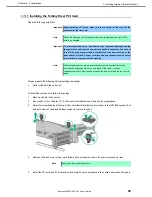
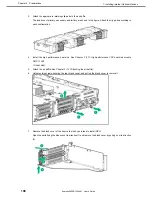
Page 111: ...h the procedure below For details see Chapter 1 1 8 Anti static Measures in Safety Precautions and Regulatory Notices Installation Please prepare the following before installing the option Parts included in the option kit T 10 hexalobular driver To install the components follow these steps 1 See steps 1 to 6 in Chapter 2 1 2 Overview of Installation and Removal for preparations 2 Raise two screw h...

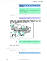
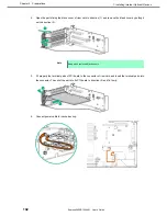
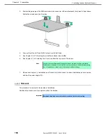
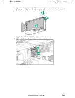
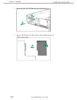
Page 112: ...vices Express5800 R120h 2M User s Guide 112 Chapter 2 Preparations 3 Remove the screw of the LOM blank cover and remove the cover 4 Align the LOM card pins to the LOM connector of the motherboard and insert it Tighten the screws firmly ...

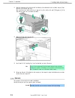
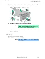
Page 113: ... to attach the top cover of the server Note In order to prevent damage of the system due to improper cooling or elevated temperature please do not activate the server or enclosure without implementing any of component or blank on all of drive bays and device bays 7 Please see Chapter 2 2 Installation and Connection in this manual to conduct installation and connection and turn the power supply ON ...

Page 114: ...e The extension battery is an extremely sensitive device Prior to installation avoid static electricity by touching the metal frame of the unit or similar Do not drop or otherwise damage the extension battery For recycling and disposal of extension batteries refer to the user s guide attached to the RAID controller or extension battery Installing the N8103 198 extension Battery Please prepare the ...

Page 115: ...1 Installing Internal Optional Devices Express5800 R120h 2M User s Guide 115 Chapter 2 Preparations 3 Remove the fan cage 4 Install the extension battery 5 Connect the cable ...

Page 116: ...ions 6 Remove all the fans from the fan cage to the state where only the fan cage is left Next align the fan cage with the device push the cage slowly from the above direction and tilt both sides of the levers to secure it 7 Push the fan from the above direction to mount it in the fan cage 1 2 2 ...

Page 117: ...ue to improper cooling or elevated temperature please do not activate the server or enclosure without implementing any of component or blank on all of drive bays and device bays 11 Please see Chapter 2 2 Installing Internal Optional Devices in this manual to conduct installation and connection and turn the power supply ON Removal The procedure for removal is the reverse of installation Re attach t...

Page 118: ...le to install and boot VMware ESXi Notes N8106 016 2x8GB microSD card installing kit USB is equipped with RAID1 function The function cannot be installed with M 2 SATA SSD This product does not include an install media of ESXi and the license Installation of USB flash memory N8106 016 017 Note In order to prevent the damage for the electronic parts start the installation of system after providing ...

Page 119: ...ert USB flash memory into the connector Removal When removing practice the steps of installing reversely When you operate the device without components install the blank cover that was installed on the device Important In order to maintain the cooling effect inside install the blank cover which you removed ...

Page 120: ... providing proper anti static treatment If a proper earth is not provided electrostatic discharge may occur Before installing the option prepare the followings T 10 hexalobular driver When installing the components follow the steps below 1 See steps 1 to 7 in Chapter 2 1 2 Overview of Installation and Removal for preparations 2 Lift up the levers on both sides of fan cage and pull the fan cage upw...

Page 121: ...pushing out the right end of it from the inside to the outside or pulling it out 6 Insert the optical disk drive from the front and fix it with a screw 7 Insert the module attached with the optical disk drive from the front and fix them with two screws 8 Connect the cables Connect the cables you disconnected to the initial positions The right side of optical disk drive blank cover Push it out from...

Page 122: ...e 122 Chapter 2 Preparations Connect the power switch module cable to the connector Connect Displayport cable to the connector Connect the optical disk drive cable to the connector SATA5 Power switch module connector Displayport connector Optical disk drive connector SATA5 ...

Page 123: ... Preparations 9 Install the fan cage Rmove all the fans from the fan cage and confirm no fan is installed in the cage Next fit the fan cage to the device push the cage slowly from above and lower the levers at both sides to fix it Push the fan from above to mount it on the fan cage 1 2 2 ...

Page 124: ...roper cooling or an elevated temperature do not operate the server or the enclosure without installing any of component or blank on all the drive bays and device bays 12 Execute the installation and connection referring to Chapter 2 2 Installation and connection of this book and then turn the power on Removal When removing practice the steps of installing reversely When you operate the device with...

Page 125: ... for the electronic parts start the installation of system after providing proper anti static treatment If a proper earth is not provided electrostatic discharge may occur Before installing the option prepare the followings Parts included in the optional kit T 10 hexalobular driver When installing the components follow the steps below 1 Back up all the data of server 2 See steps 1 to 7 in Chapter ...

Page 126: ... you to dismantle it 5 Insert a front 2x 2 5 inch drive cage N8154 96 or N8118 317 from the front and fix them with two screws 6 Connect the power cable of a front 2x 2 5 inch drive cage N8154 96 or N8118 317 7 Connect the data cable of front 2x 2 5 inch drive cage N8154 96 or N8118 317 as below in the circumstance Connecting to SAS SATA drive cage N8154 96 and the mother board ...

Page 127: ...ss5800 R120h 2M User s Guide 127 Chapter 2 Preparations Connecting to SAS SATA drive cage N8154 96 and RAID controller Connecting to SAS SATA drive cage N8154 96 and SAS expander Connecting to PCIe SSD drive cage N8118 317 and PCIe SSD riser card ...

Page 128: ...28 Chapter 2 Preparations 8 Remove all the fans from the fan cage and confirm no fan is installed in the cage Next fit the fan cage to the device push the cage slowly from above and lower the levers at both sides to fix it 9 Push the fan from above to mount it on the fan cage ...

Page 129: ...r blank on all the drive bays and device bays 13 Execute the installation and connection referring to Chapter 2 2 Installation and connection of this book and then turn the power on Removal When removing practice the steps of installing reversely When you operate the device without components install the blank cover that was installed on the device Important To prevent personal injury electrical s...

Page 130: ...quipment damage unplug the power cord and ensure no power is supplied to the server You cannot turn off the system power supply completely by the power button on the front panel Until the AC power cord is unplugged the power supply circuit is still active in some parts of the machine Please prepare the following before installing the options Parts included in the option kit T 10 Hexalobular driver...

Page 131: ...se the screw handles at the top of the primary riser card and turn them to the left 180 degrees Then hold both sides of cage and lift them upright to remove the cage 4 In case of secondary riser unfasten the screws x2 securing the rear blank cover and pull the blank cover upward to remove it 5 Install a RAID controller PCI board or an SAS expander if necessary ...

Page 132: ... the slot Then fix the riser card Next raise the screw handle at the top of the cage and turn the handle to the right 180 degrees to fix the cage Then put down the screw handle as before 7 Connect the power cord and the data cable of the backplane of rear drive cage Connecting the primary drive cage backplane with SAS expander Connecting the secondary drive cage backplane with SAS expander 8 Attac...

Page 133: ...Tertiary Riser Drive Cage N8154 95 Important To prevent personal injury electrical shock or equipment damage unplug the power cord and ensure no power is supplied to the server You cannot turn off the system power supply completely by the power button on the front panel Until the AC power cord is unplugged the power supply circuit is still active in some parts of the machine Please prepare the fol...

Page 134: ...se the screw handle at the top of the riser card turn it 180 degrees to the left hold the both ends of the cage and lift it straight up to remove it 3 Unfasten the screws x3 securing the tertiary blank cover and pull the blank cover upward to remove it 4 Insert the tertiary drive cage from the upward direction and secure it with the screws x4 ...

Page 135: ... x4 6 Attach a drive or a dummy tray to the drive cage 7 If you removed a riser card in the step2 fit the terminal of riser card to the slot on the mother board and insert the terminal firmly into the slot Then fix the riser card Next raise the screw handle at the top of cage and turn the handle to the right 180 degrees to fix the cage Then put down the screw handle as before If you removed a blan...

Page 136: ...2M User s Guide 136 Chapter 2 Preparations 8 Connect the power cord between drive backplane and motherboard In case of 12x 3 5 inch drive configuration and power single cable connection In case of 24x 2 5 inch drive configuration and power Y cable connection ...

Page 137: ...to prevent damage of the system due to improper cooling or elevated temperature please do not activate the server or enclosure without implementing any of component or blank on all of drive bays and device bays 11 Please see Chapter 2 2 Installation and Connection in this manual to conduct installation and connection and turn the power supply ON Removal The procedure for removal is the reverse of ...

Page 138: ...his option the 12x 3 5 inch drive must be fully installed in the front bay In addition a high performance fan should be installed To install the components follow these steps 1 Back up all data in the server 2 See steps 1 to 6 in Chapter 2 1 2 Overview of Installation and Removal for preparations 3 If the secondary riser card is installed remove it If this 3x 3 5 inch rear drive cage is installed ...

Page 139: ...crews x3 securing the tertiary riser blank cover and pull the cover upward to remove it 5 Attach a rubber bush on a slotted hole on the bottom of the 3 x 3 5 drive cage install the cage from the top and secure with screws x3 6 Install a 3 5 inch drive or a dummy tray 7 If you installed a drive connect the power cord ...

Page 140: ...em due to improper cooling or elevated temperature please do not activate the server or enclosure without implementing any of component or blank on all of drive bays and device bays 10 Please see Chapter 2 2 Installation and Connection in this manual to conduct installation and connection and turn the power supply ON Removal The procedure for removal is the reverse of installation Re attach the bl...

Page 141: ...he options Parts included in the option kit The option must be attached under the following conditions A 1U heat sink is required to attach this option Attach the 1U heat sink before attaching the mid plane drive cage If you would like to attach a TPM attach the TPM before attaching the mid plane drive cage If you would like to attach a Type a mezzanine type AROC RAID controller attach the control...

Page 142: ...motherboard 4 Lift up the latch of the drive cage 5 Install the drive cage Note Do not drop the drive cage onto the motherboard Dropping the drive cage onto the motherboard may damage the motherboard or other components Remove all drives and attach the drive cage to the device using both hands 1 Attach the back side of the mid plane drive cage to the standard positioning pins 2 Position the remain...

Page 143: ...lunger pin on the back right of the mid plane drive cage and slowly lower the mid plane drive cage until it interlocks with the plunger pin The mid plane drive cage is attached in this manner 6 Mount the drive 7 To fix the mid plane drive cage in this position press down on the latch 8 Install all the riser cards ...

Page 144: ...er Note In order to prevent damage of the system due to improper cooling or elevated temperature please do not activate the server or enclosure without implementing any of component or blank on all of drive bays and device bays 11 Please see Chapter 2 2 Installation and Connection in this manual to conduct installation and connection and turn the power supply ON Removal The procedure for removal i...

Page 145: ...stall the system after conducting the appropriate anti static treatment There is a possibility of causing electrostatic discharge if appropriate grounding wire treatment is not conducted Installation Please prepare the following before installing the options Parts included in the option kit T 10 hexalobular driver To install the components follow these steps 1 See steps 1 to 6 in Chapter 2 1 2 Ove...

Page 146: ... blank cover as shown below 3 Install the serial cable A If a tertiary riser is not attached 1 Position the serial cable as shown below 2 Attach the serial cable connector 3 Secure the external connector with screws x2 4 Remove the paper backing of the double sided tape and press it against the cable at the indicated location to fix the cable in place ...

Page 147: ...event damage of the system due to improper cooling or elevated temperature please do not activate the server or enclosure without implementing any of component or blank on all of drive bays and device bays 5 Please see Chapter 2 2 Installation and Connection in this manual to conduct installation and connection and turn the power supply ON Removal The procedure for removal is the reverse of instal...

Page 148: ...ts when building a RAID System The number of hard disk drives required varies in each RAID level If the optional RAID Controller N8103 189 195 is used the RAID System cannot be built in RAID5 RAID6 RAID50 RAID60 RAID level The minimum number of hard disk drives required to set up a RAID System N8103 189 195 N8103 190 191 201 RAID 0 1 1 RAID 1 2 2 RAID 5 3 RAID 6 3 RAID 10 4 4 RAID 50 6 RAID 60 6 I...

Page 149: ...r 2 Preparations 1 27 Attaching the air baffle The procedure for removal is the reverse of installation Important Keep the air baffle close to the device when attaching it so the cables are not pulled Attaching the air baffle without keeping it close to the device may result in damage ...

Page 150: ...ad driver Leave the hood latch open and place the top cover straight on the unit so that it is securely inserted in the frame Adjust the position of the top cover so that it protrudes approximately 1 25 cm 0 5 inch from the rear of the unit Press down on the hood latch Slide the top cover until it is completely closed Tighten the security screw on the hood latch with hexalobular screwdriver T 10 o...

Page 151: ...pes and or rotational frequencies cannot be used together When performing RAID constructions use hard disk drives of the same capacity type and rotational frequency within the same group pack If you are using only one hard disk drive please install it in the bay with the smallest lowest device number When drives that are grouped together into the same drive array for the most efficient use of stor...

Page 152: ...e the same specifications capacity rotational speed and standard for each Disk Array 1 See Chapter 2 1 2 Overview of Installation and Removal for preparations Locate the slot where you install the hard disk drive Install hard disk drives in ascending order of port number 2 Remove the dummy tray Dummy trays are installed in every slot Note Keep the removed dummy trays for future use 3 5 inch drive ...

Page 153: ...t it into the slot Note Push it all the way until the handle s lock touches the frame Hold the tray firmly with both hands 5 Slowly close the handle The tray is locked making a clicking sound Hold the tray firmly and insert it into the slot Note When you push the drive into the slot confirm the handle got hooked on the frame 6 Check the drive status via definition of the drive LED ...

Page 154: ... the opening time of the top cover 1 Check the drive status via definition of the drive LED 2 Back up all server data in the drive 3 Unlock the handle of the tray Grasp the handle and slowly pull it to remove the drive If you transfer or dispose of the removed hard disk drive see Chapter 1 1 Relocation and Storage in Maintenance Guide to erase data Important NEC assumes no liability for data leaka...

Page 155: ...PRESSBUILDER DVD media Note In order to prevent damage of the system due to improper cooling or elevated temperature please do not activate the server or enclosure without implementing any of component or blank on all of drive bays and device bays 1 Remove the drive blank if it is installed 2 Prepare the drive Press the removal prohibit switch to open the release handle 3 Hold the tray firmly and ...

Page 156: ... data leakage should the product be transferred to a third party without erasing the data 1 Press the power switch The LED of the removal prohibit switch lights up and flashes Do not press this switch while the LED is lit Note Do not remove the PCIe SSD from the drive bay if the LED of the removal prohibit switch is flashing The flashing LED of the removal prohibit switch indicates that the device...

Page 157: ...e capacity Make sure that the two power supply units have the same part number and the same label color If the two power supply units are inappropriate the system may become unstable to be shut down Note In order to prevent damage of the system due to improper cooling or elevated temperature please do not activate the server or enclosure without implementing any of component or blank on all of dri...

Page 158: ...d power cords When the power cord is connected the AC power LED on the power unit will turn green Power on the server Confirm by STATUS LED or on POST screen that there are no errors related to the power supply units See Chapter 3 1 IML Error Message in Maintenance Guide for details on POST error messages If AC POWER LEDs are off reinstall the power supply units If the same error occurs contact wi...

Page 159: ...he LED AC power LED is off Power off the server Tips In the redundant power configuration with two power supply units and if either one of power supply units fails the failing power supply unit can be replaced with the system power on Disconnect the AC power cord from the failing power supply unit Push the lever of the failing power supply unit toward inside and pull the power supply unit while ho...

Page 160: ...n the upper and lower sides of the front bezel 2 Fit the right side from the front view of the front bezel into a recess on the front part of the device push the left side lever to the right set in place the left side of the device and then release the lever so that it will be locked Check whether the front bezel is securely locked by pulling it lightly in front 1 2 ...

Page 161: ...ptional Devices Express5800 R120h 2M User s Guide 161 Chapter 2 Preparations 3 Insert the key and rotate it clockwise while pressing until it is locked into place Important Be careful not to press the POWER Switch Unlock Lock ...

Page 162: ...he specified environment Do not connect the ground wire to a gas pipe CAUTION Be sure to observe the following precautions to use the server safely Failure to observe the precautions may cause burns injury and property damage For details refer to Safety Precautions and Regulatory Notices Do not carry or install the server only by a single person Do not install the server so that the load may be co...

Page 163: ... outlet of another device with large power consumption Place near equipment that generates power noise e g contact spark at power on power off of commercial power supply through a relay Environment where operation of the server is not guaranteed Space and air flow requirements For easier repairing and improvement of ventilation follow the space requirements when you determine the install location ...

Page 164: ...ke sure that temperature inside the rack does not exceed the maximum specifications Make sure that the manufacturer s TMRA specification is not exceeded When using racks of other companies the following additional requirements must be met in order to improve the ventilation for preventing damages to the equipment Power requirements The installation of this equipment must be performed by a qualifie...

Page 165: ...edly to the branch circuit of the building or using a PDU equipped with a non removable cord connected to the industrial plug NEMA locking plugs or IEC 60309 compliant plugs are suitable for this purpose For the server an extension cord with the outlet for general use is not recommended to be used Connecting DC power cable and DC power supply Important To prevent injuries due to electric shock or ...

Page 166: ... or power off devices should not be located on the grounded circuit conductor between the DC source and the connection point of the ground electrode conductor For connecting the DC power cable to DC power supply follow the procedure below 1 Cut the DC power cord at least 150 cm 59 06 in in length 2 If ring tongs are required for the power supply use a crimping tool to attach the ring tongue to the...

Page 167: ...utions to use the server safely Failure to observe the precautions may cause burns injury and property damage For details refer to Safety Precautions and Regulatory Notices Do not drop Do not leave the server being pulled out Do not install with the cover removed Do not get your fingers caught Important Temperature increases and airflow in the rack If multiple devices are installed or if the insid...

Page 168: ...ver Ball bearing type rack rail for 3 5 inch drive model no inner rail used N8143 134 Slide rail for 2U rack server Slide rail type rack rail for 3 5 inch drive model inner rail used Important Rail for left side has different shape from that for right side Make sure the orientation of rails to properly install them 1 Slide rail for 2U rack server N8143 133 134 Checking the inner and outer rails Ch...

Page 169: ...r of the inner rail clicks to be securely locked Removing the inner rail Lifting a little the metal plate part located around the center of the inner rail then the lock will be released Slide it forward in the unlocked state and it can be removed Attaching the outer rail to the rack Insert the round protrusion on the outer rail into the square hole of the 19 inch rack Make sure that it makes a cli...

Page 170: ... outer rails Remove outer rails from the rack in the following procedure 1 See Chapter 2 2 1 7 Installing the server to the rack or removing it from the rack 2 Removal procedure to remove the server from the rack 2 Reduce the slide rail of the outer rail In case the slide rail is locked in the middle continue pushing the rail stopper on the side of the rail to reduce the slide rail 3 Push and rele...

Page 171: ... the outer rails Check the direction of the outer rail Since there are markings of Right and Left on the outer rail check the proper directions of right and left with it Likewise check the directions of front and back with the markings of Front and Rear Marking of Front right Left rail Right rail Marking of Front left Marking of Rear Marking of Rear ...

Page 172: ...t Confirm that the rail are securely locked so that they will not fall off Tips Although the rail may be somewhat unsteady it is not defective Removing the outer rails Remove outer rails from the rack in the following procedure 1 See Chapter 2 2 1 7 Installing the server to the rack or removing it from the rack 2 Removal procedure to remove the server from the rack 2 Push and release the unlocking...

Page 173: ...ection Express5800 R120h 2M User s Guide 173 Chapter 2 Preparations 4 Push and release the unlocking lever on the rear side of the outer rail toward the outside of the rack and push the rail backward of the rack to remove it ...

Page 174: ...er with single person Do not drop Do not leave the server being pulled out Do not install with the cover removed Do not get your fingers caught 1 Slide rail for 2U rack server N8143 133 134 a Installation Mount the server to a rack in the following procedure Important Always install the server with two or more persons 1 With two or more persons firmly hold the server and mount it to the rack 2 Mak...

Page 175: ...luded cable tie strip to the rear side of the rack attach the tie strip to the mounting hole of the outer rail as shown below 4 If you like to secure the unit to the rack with screw open the lid of the edge part of the unit and fasten the Hexalobular screw inside with a Hexalobular screwdriver to secure the unit to the rack ...

Page 176: ...move the front bezel Open the lids of the unit fixing screws on both sides of the device Then remove the fixing screws inside with Hexalobular screwdriver if the device is screwed on If the device is not screwed on you can unlock the device just by opening the lid Slide the unit forward and remove from the rack while holding it securely In case the unit is locked in the middle continue pushing the...

Page 177: ...edure Important Always install the server with two or more persons 1 Pull out the left and right outer rails until they are completely locked to the front side 2 Hold the unit securely by two or more persons and lift it to the height of the rack rail 3 Carefully install the device to the rail while confirming that the protrusion part of the device is correctly inserted in the groove of the rail in...

Page 178: ...ure the unit to the rack with screw open the lid of the edge part of the unit and fasten the Hexalobular screw inside with a Hexalobular screwdriver to secure the unit to the rack b Removal procedure Remove the server from the rack in the following procedure Important At least two persons are required to remove the server from rack Make sure that the server is turned off and then disconnect the po...

Page 179: ...9 Chapter 2 Preparations Open the lids of the unit fixing screws on both sides of the device Then remove the fixing screws inside with Hexalobular screwdriver if the device is screwed on If the device is not screwed on you can unlock the device just by opening the lid ...

Page 180: ... stopper button on the side of the rail and lift the device above the rails in the order of 1 2 3 4 to remove it from the rail Important Be careful not to get your fingers caught in the rails or lever Important While more than one person is supporting the bottom part of the server slowly pull out the server Do not apply pressure on the server from top when it is being pulled out Doing so cause the...

Page 181: ...e death or serious injury For details refer to Safety Precautions and Regulatory Notices Do not hold the power plug with wet hands Do not connect the ground wire to a gas pipe CAUTION Be sure to observe the following precautions to use the server safely Failure to observe the precautions may cause burns injury and property damage For details refer to Safety Precautions and Regulatory Notices Use o...

Page 182: ... with leased line FRONT Data LAN Ports REAR Device with serial interface USB device Display unit Hub switching hub etc Finally connect the provided power cord to an outlet For connecting with UPS refer to the next section 1000BASE T 100BASE TX 10BASE T 1000BASE T 100BASE TX 10BASE T Management LAN port 8x 3 5 inch drive model USB device ...

Page 183: ...Power Supply UPS To connect the power cord of the server to a UPS use the connector output on the rear of the UPS For details refer to the manual supplied with the UPS When the power cord is connected to a UPS change the settings from System Utility in order to link the server with the power supply from the UPS To change the settings select System Configuration BIOS Platform Configuration RBSU Sys...

Page 184: ...ement arm A cable management arm can be installed to the unit for combining the multiple cables connected to the device Install the cable management arm in the following steps 1 Attach the power cord anchor 2 Insert the two fixed parts of the cable management arm into the outer rail and the inner rail behind the rack ...

Page 185: ...le cables in the binding belt and secure them 4 Insert the fixed parts of the supplied cable management arm into the outer rail on the opposite side Removing the cable management arm 1 Press the lock release button on the fixed part of the cable management arm to release the lock and pull it out forward ...

Page 186: ... Connection Express5800 R120h 2M User s Guide 186 Chapter 2 Preparations 2 Press the lock release button on the two fixed part on the opposite side of the cable management arm to release the lock and pull it out forward ...

Page 187: ...Description of system utility Describes how to set up the system 3 iLO 5 Describes iLO 5 installed in the unit 4 EXPRESSBUILDER and Starter Pack EXPRESSBUILDER helps you to install Windows and maintain the server 5 Installing Software Components You can install Windows and bundled software by following the instructions in Installation Guide Windows 6 Turning off the Server Turn off power when not ...

Page 188: ...ontrol unit such as uninterruptible power supply UPS make sure that the power supply control unit is turned ON Remove Front Bezel When the STATUS lamp flashes green once per second wait until the lamp lights in steady state Press POWER Switch at the front of the server POWER LED flashes green once per second and after a while logo appears on the display Important Do not connect disconnect USB devi...

Page 189: ... an initialization message is displayed The message to tell initialization of a memory and a PCI device Note While the initialization messages are being displayed the screen may change several times There is no problem in operation by this If an option VGA controller is connected or depending on system utility settings logos or initialization messages may not be displayed Initialization message is...

Page 190: ...e instruction documents attached to each option board Necessary key inputs are different depending on option boards installed so you are requested to operate according to messages 4 The OS starts when POST is completed Tips When no bootable device is connected the following message is displayed by terminating POST No bootable devices ware detected Please attach a UEFI bootable device System will a...

Page 191: ...ce and options installed Enabling and disabling system functions Display of system information Selection of Primary Boot Controller Configuration of Memory Option Selection of language Start of pre boot environment such as built in UEFI shell or EXPRESSBUILDER Regarding the details of System Utility see Chapter 2 1 System Utility of Maintenance Guide 2 2 Starting SETUP Utility Run POST following C...

Page 192: ...t press F12 Key F12 Save and Exit In case you cancel your change and exit press ESC Key Exit Tips To put the setting back to the default values press F7 Key F7 Load Defaults The default value might be different from the factory setting iSCSI Configuration menu in Network Options menu cannot be put back to the default values The default language of System Utility is English ...

Page 193: ...y selected key key Change the value parameter of the selected item You cannot use this key when a menu which has on the left is selected Enter key Press this key to determine the selected parameter Esc key Pressing this key cancels pop up window On the submenu pressing this key takes you to the previous screen On the top menu the following window is displayed Choose OK to close System Utility Indi...

Page 194: ...System Utility Press Esc key to go back to the original screen F7 key The following screen is displayed To put the parameters of System Utility back to the default setting select Restore Defaults and Reboot This operates in the same manner as Restore Default System Settings in the System Default Options menu For details refer to Chapter 2 1 System Utilities in the Maintenance Guide Note iSCSI Conf...

Page 195: ...Express5800 R120h 2M User s Guide 195 Chapter 3 Setup F12 key The following screen is displayed If you choose Yes the parameter you set is saved and then a message urging to reboot is displayed If you select Reboot the device restarts ...

Page 196: ...e Windows Set to Local Time at System Configuration BIOS Platform Configuration RBSU Date and Time Time Format Included in line 16 Set up following the pre install checklists in the installation guide below For Windows Chapter 1 Installing Windows If you use Linux Set System Configuration BIOS Platform Configuration RBSU Date and Time Time Format to Coordinated Universal Time UTC Set up following ...

Page 197: ...n compliance with the checklist before setup in the installation guide of your OS For Windows Chapter 1 Installing Windows Set the Boot Mode to Legacy BIOS Mode according to your OS Change System Configuration BIOS Platform Configuration RBSU Boot Options Boot Mode to Legacy BIOS Mode 1 The setting must be done in compliance with the checklist before setup in the installation guide of your OS Chan...

Page 198: ...ich is needed for tboot Trusted Boot enabled Install optional TPM kit and set to Enabled in System Configuration BIOS Platform Configuration RBSU Server Security Intel R TXT Support Do not disable TPM with the TPM management module after setting TXT Support to Enabled to start OS You may not be able to change TPM Support and TXT Support In that case execute F7 Load Defaults UPS Powerlink When the ...

Page 199: ...ly after the power is turned OFF While POST Immediately after POST Tips After completion of POST execution or the powering OFF it may take several minutes to reach downloadable state Please wait for a while to start download The time required to reach downloadable state may vary depending on configuration or operating status of the unit Restore The restore of system configuration is established by...

Page 200: ...and to log in iLO of the controlled server Initial user name and initial password which are required to log in are written on a slide tag attached to the controlled server 4 Execute types command and confirm the parameter on whose lead BIOS is displayed 5 Select BIOS in select command As the argument of select command specify the parameter you confirmed in step 4 6 Execute save command to backup s...

Page 201: ...ed in step 4 Tips The serial number of system information and product ID are not restored 7 When the power of device is OFF make it ON Or in case OS is running reboot Tips Since the changes of system configuration are applied during POST please wait until POST is completed Then the device restarts automatically Notes Configurations whose backup and restore are possible are the menus under System U...

Page 202: ...ent between the time of restoring and the time of backup You cannot restore some system configurations in case there is a difference in hardware configuration between the time of back up and that of restore If you restore with your OS running restart the device in order to reflect the system configuration to it Backup and restore of system configuration file may take several minutes In case you us...

Page 203: ...r and configure SNMP notification Email alert and notifications in Remote Syslog Active Health System Log AHS Log Download Active Health System Log In case the support is needed AHS Log file may need to be sent to NEC or taken by maintenance staff iLO Cooperative Network Management By using iLO Cooperative Function you can detect and manage multiple servers at once without using management softwar...

Page 204: ...Console IRC Pre OS only Pre OS only Global Team Collaboration by 6 server administrators at the maximum via IRC Recording and playback of video via IRC Recording and playback of Virtual Serial Port Remote Console of text base via SSH Email alerts Remote Syslog Advanced Power Management power graph dynamic power capping iLO Collaborative Management iLO Collaborative Detection Remote Serial Console ...

Page 205: ...r Run POST following Chapter 3 1 1 1 POST sequence After a while the following message is displayed on the lower part of the screen Press the F9 key while the message is being displayed to launch System Utilities From the menu of System Utilities select System Configuration BMC Configuration Utility View example when BMC Configuration Utility is selected ...

Page 206: ...gement specialized LAN connector to connect to the network Follow the setting in Step 4 to access iLO5 from Web browser of the administrator PC iLO5 contains default username password and DNS name set at the time of shipment The default username password and DNS name are written on a slide tag attached to a device to which iLO is installed Using these values and the network setting you configured ...

Page 207: ... Change password without fail at the time of initial setup If you use the initial password unchanged and then you suffer unauthorized access we will not hold any responsibility at all Even if you change the initial password less strong ones ones including fewer figures or easily conceivable ones 123456789 abrade Administrator etc are difficult to prevent unauthorized accesses Please change to a st...

Page 208: ...install SPP automatically when installing OS SPP must be installed after installing OS Application installation Installs NEC ESMPRO RESTful Interface Tool and other applications Manuals Stores manuals for applications 4 2 Usage of EXPRESSBUILDER Run EXPRESSBUILDER by pressing F10 key during POST when you want to configure RAID array or install OS For details see Chapter 2 3 Details of EXPRESSBUILD...

Page 209: ...g Software Components Express5800 R120h 2M User s Guide 209 Chapter 3 Setup 5 Installing Software Components Continue to install software components such as OS See the instructions below Installation Guide Windows ...

Page 210: ...be supplied to the system even if the server is in standby mode When shutting down the server use one of the following methods Press and release the POWER switch This method shuts down applications and OS in the correct order before the server enters standby mode Press and hold the POWER switch for 4 seconds or more to force the server to enter standby mode This method forces the server to enter s...

Page 211: ...Express5800 R120h 2M User s Guide 211 NEC Express5800 Series Express5800 R120h 2M Appendix 1 Specifications 2 Glossary 3 Revision Record ...

Page 212: ... 1 6TB When an optional HDD cage is added 3 5 inch HDD SATA190TB 19x10TB 2 5 inch HDD SATA 12TB 6x2TB but must be 3 5HDDx16 SAS 10 8TB 6x1 8TB 2 5 inch SSD SATA 23 04TB 6x 3 84TB SAS 5 76TB 6x 960GB When an optional HDD cage is added Hot swap Capable Interface specification and RAID configuration SATA 6Gb s RAID 0 1 5 6 10 50 60 Option SAS 12Gb s RAID 0 1 5 6 10 50 60 Option Optical disk drive Con...

Page 213: ...utions and Regulatory Notices front bezel Install OS OS supported NEC support Microsoft Windows Server 2012 R2 Standard Microsoft Windows Server 2012 R2 Datacenter Microsoft Windows Server 2016 Standard Microsoft Windows Server 2016 Datacenter Red Hat Enterprise Linux 7 3 or later 4 VMware ESXi 6 0 Update3 VMware ESXi 6 5 Update1 Operation Check OS Regarding the latest operational information refe...

Page 214: ...cessor 2GHz 20C 40T 27 50MB TDP 125W Xeon Gold 6140 Processor 2 30 GHz 18C 36T 24 75MB TDP 140W Xeon Gold 6142 Processor 2 60 GHz 16C 32T 22MB TDP 150W Xeon Gold 6144 Processor 3 50 GHz 8C 16T 24 75MB TDP 150W Xeon Gold 6146 Processor 3 20 GHz 12C 24T 24 75MB TDP 165W Xeon Gold 6148 Processor 2 40 GHz 20C 40T 27 50MB TDP 150W Xeon Gold 6150 Processor 2 70 GHz 18C 36T 24 75MB TDP 165W Xeon Gold 615...

Page 215: ...d from T1 to T100 This is sometimes abbreviated as 6lobe iLO A built in controller that supports the IPMI version 2 0 protocol The controller is called as iLO5 because this server adopts a generation 5 version controller NEC ESMPRO ServerAgentService Software for monitoring the server This works with NEC ESMPRO Manager You can choose Service Mode or Non Service Mode when installing this software S...

Page 216: ... SPP instruction manual application and other software for the server This must be installed before using OS on the server Starter Pack is provided as an optional product and ISO data on our website System Maintenance Switch A DIP switch on motherboard This switch can enable disable initialization password iLO settings and other functions of maintenance System Utilities System Utilities is a built...

Page 217: ...4 Appendix 3 Revision Record Document Number Date Issued Description First edition April 2018 Newly created Second edition July 2018 The following were modified 1 7 TPM Kit N8115 35 1 8 Processor CPU 1 10 High performance CPU heat sink module N8101 1286 1U heat sink ...

Page 218: ... R120h 2M User s Guide July 2018 NEC Corporation 7 1 Shiba 5 Chome Minato Ku Tokyo 108 8001 Japan NEC Corporation 2018 The contents of this manual may not be copied or altered without the prior written permission of NEC Corporation ...

Reviews: