4. Names and Functions of Parts
Express5800/R120h-2M User’s Guide
29
Chapter 1 General Description
4.5
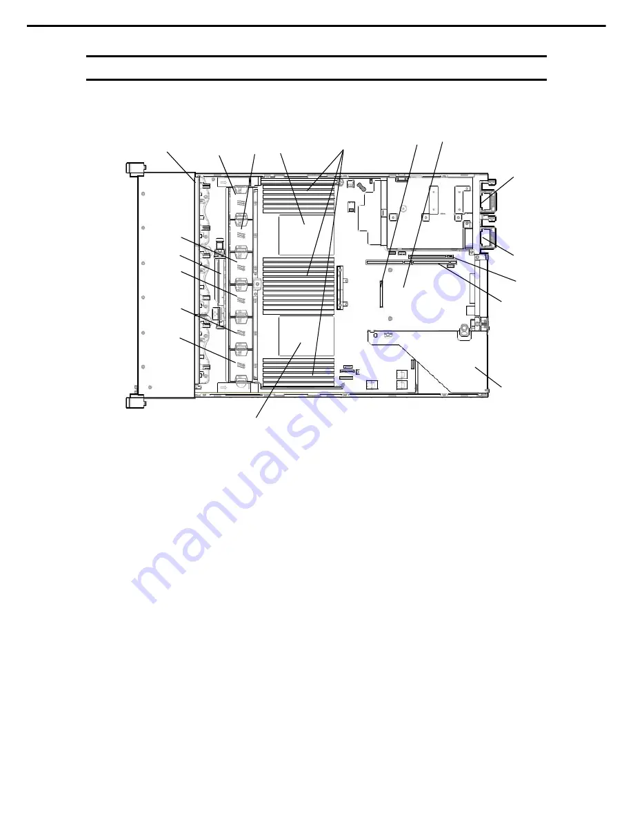
Internal View
The diagram omits the air duct.
(1) Backplane
(2) Cooling
Fan
-1 FAN1 (option)
-2 FAN2 (option)
-3 FAN3
-4 FAN4
-5 FAN5
-6 FAN6
FAN3 to FAN6 are factory installed. FAN 1
and 2 are required in 2-CPU configuration.
(3) Processor (CPU, installed under the heat
sink)
-1 CPU1 (required option)
-2 CPU2 (option)
(4) DIMM
(option)
(5) Slot for RAID Controller
(6) Motherboard
(7) Primary
Riser
Card
Standard riser is standard-installed
Changeable by option
(8) Secondary Riser Card connector
Riser card/cage are optional.
(9) Tertiary Riser Card connector
Riser card/cage are optional.
(10) Power Supply Unit
The numbers after the parenthesized numbers
indicate slot numbers.
-1
PSU1 (required option)
-2
PSU2 (optional)
(11) Battery for RAID controller
(1)
(3)-2
(7)
(10)-1
(9)
(11)
(2)-1
(2)-2
(2)-3
(2)-4
(2)-5
(4)
(6)
(2)-6
(5)
(3)-1
(8)
(10)-2


