


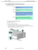

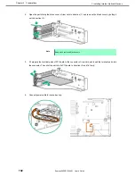


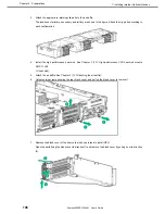
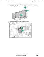
1. Installing Internal Optional Devices
Express5800/R120h-2M User’s Guide
94
Chapter 2 Preparations
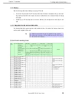
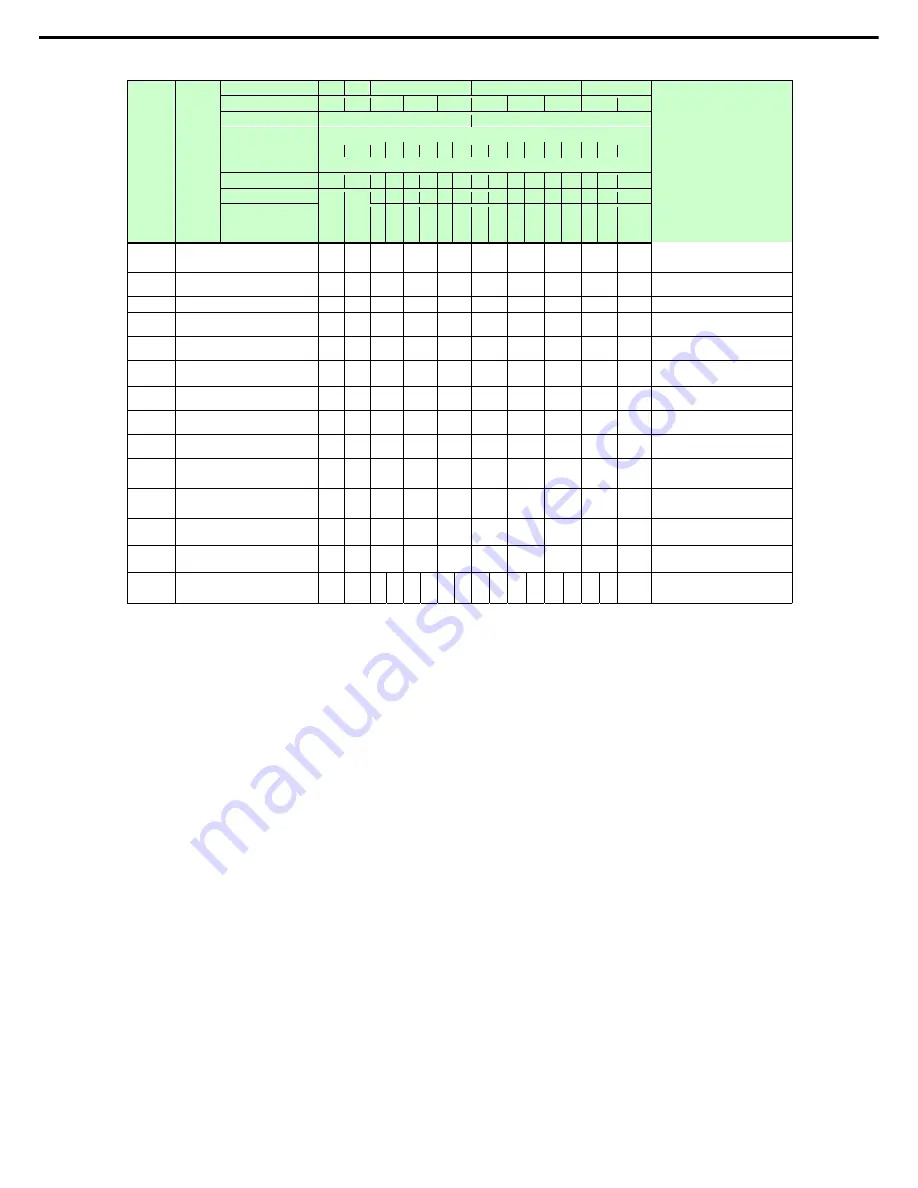
Part
number
Part name Riser card name
RAID LOM
1st riser card *3
2nd riser card *3
3rd riser card*3
Remarks
Slot number
-
-
SLOT1 SLOT2 SLOT3
SLOT4
SLOT5
SLOT6
SLOT7
SLOT8
CPU connected
CPU1
CPU2
PCI standard
PCIe3.0
PCI slot performance *1
x8
x8
x8 x16 x8 x16 x8 x16 x8 x16 x8 x16 x8 x16 x8 x16
x8
Bandwidth/lane *1
8Gb/s
PCI board type *2
-
-
x8 x16 x8 x16 x8 x16 x8 x16 x8 x16 x8 x16 x8 x16
x8
Slot size
Dedic
ated
to
RAID
Dedic
ated
to
LOM
FH FH FH FH FH FH FH FH FH FH FH FH FH FH
FH
Available size
FL FL HL HL HL HL FL
FL
HL HL HL HL FL
FL
HL
N8104-181
1000BASE-T Card (4ch)
[PCI Express 2.0(x4)]
-
-
1 3 5 2 4 6 7 8
Network cables with RJ-45 plug
covers cannot be used.
N8104-182
10GBASE-T Card (2ch)
[PCI Express 2.0(x8)]
-
-
1 3 5 2 4 6 7 8
N8104-183 10GBASE-T interface board (2ch)
-
-
1 3 5 2 4 6 7 8
N8104-184
10GBASE-T interface board
(2ch)[PCI Express 3.0(x4)]
-
-
1 3 5 2 4 6 7 8
N8104-187
25GBASE Interface basic board
(SFP28/2ch)
-
-
1 3 5 2 4 6 7 8
N8104-185
10GBASE
Basic Card
(SFP+/2ch)
[PCI Express 2.0(x8)]
-
-
1 3 5 2 4 6 7 8
N8104-186
10GBASE Basic Card(SFP+/2ch)
[PCI Express 3.0(x8)]
-
-
1 3 5 2 4 6 7 8
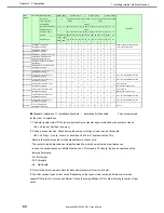
N8190-163
Fibre Channel controller (1ch)
[PCI Express 3.0(x8)]
-
-
1 3 5 2 4 6 7 8
Can
’
t mix with N8190-165/-166
N8190-164
Fibre Channel controller (2ch)
[PCI Express 3.0(x8)]
-
-
1 3 5 2 4 6 7 8
Can
’
t mix with N8190-165/-166
N8190-165
Fibre Channel Controller (1ch)
[PCI Express 3.0(x8)]
-
-
1 3 5 2 4 6 7 8
Can’t mix with
N8190-163/-164/-171/-172
N8190-166
Fibre Channel Controller (2ch)
[PCI Express 3.0(x8)]
-
-
1 3 5 2 4 6 7 8
Can’t mix with
N8190-163/-164/-171/-172
N8190-171 Fibre Channel controller (1ch)
[PCI Express 3.0(x8)]
-
-
1 3 5 2 4 6 7 8
Can
’
t mix with N8190-165/-166
N8190-172 Fibre Channel controller (2ch)
[PCI Express 3.0(x8)]
-
-
1 3 5 2 4 6 7 8
Can
’
t mix with N8190-165/-166
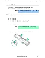
N8105-51
GPU Computing Card
[PCI Express 3.0(x16)]
-
-
-
1
-
3
-
5
-
2
-
4
-
6
-
7
-
Up to 1
●
Standard Installation
○
Installation Available
-
Installation Not Available
The numbers stand
for the order of installation.
*1 The data transfer rate of PCI slot is calculated from a transfer band multiplied by the number of lanes.
<Ex.> x8 lanes = 64Gbps (one way)
*2 Shows a connector size. Cards having the number of plugs or lower can be connected.
<Ex.> x8 Plug
→
x1card, x4card, or x8card can be fit in. x16card cannot be fit in.
・
Refer to the technical guide for the detailed feature of each card.
・
The contents inside brackets next to part names show card’s own maximum performances.
・
In case the performances are different between a PCI slot and a PCI board, the device operates on the
lower performance.
・
FH: Full height
・
FL: Full length
・
HL
:
Half length
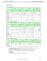
*3 Refer to the list of riser card slots for slot performance/ slot form of each slot.
*4 We offer various types of riser cards. Depending on the types of riser cards, performance, form and
support PCI card of a slot may be different. Check the compatibilities of PCI cards referring to the list of riser
cards.


