background image

Summary of Contents for FD1165

Page 1: ...FDl165 Flexible DiskDrive Maintenance Manual NEe NEe Info mation Systems lnc 819 000090 2001 10 82 ...

Page 2: ...ion must be determined by the customer and is not warranted by NECIS This manual is as complete and factual as possible at the time of pr inting however the information in this manual may have been updated since that time NEC Information Systems Inc reserves the right to change the functions features or specifications of its products at any time without notice NEC Information Systems Inc has prepa...

Page 3: ...tructions and User s Responsibilities to Prevent Radio Freguency Interference Manufacturer s Instructions The user must observe the following precautions in install ing and operating this device 1 Operate the equipment in strict accordance with the manufacturer s instructions for the model 2 Ensure that the unit is plugged into a properly grounded wall outlet and that the power cord sup plied with...

Page 4: ...e in equipment power source If these a ttempts are unsuccessful install one or all of the following devices 1 Line isolation transformers 2 Line filters 3 Electro magnetic shielding If necessary the user should consult the dealer NEC or an experienced radio television technician for additional sug gestions The user may find the following booklet prepared by the Federal Communications Commission to...

Page 5: ...te Protect Sensor Media In Sensor Collet Assembly Printed Circuit Board PCB Variable Frequency Oscillator Optional Display Lamps Front Panel Movable Door Handle Door Lock Solenoid 1 2 1 2 1 3 1 3 1 3 1 3 1 4 1 4 1 4 1 4 1 4 1 4 1 4 1 4 1 5 1 5 1 5 1 5 1 3 SPECIFICATIONS 1 5 CHAPTER 2 INSTALLATION AND OPERATION 2 1 2 2 PRELIMINARY INSPECTION UNPACKING AND REPACKING 2 1 2 1 ENVIRONMENTAL REQUIREMENT...

Page 6: ...afe Jumper FR Door Lock Jumpers DL DR DH 2 4 1 2 4 2 2 4 3 2 8 1 2 8 2 2 8 3 2 8 4 2 8 5 2 8 6 2 5 2 6 2 7 2 8 OPERATING THE FDl165 DISPLAY LAMPS 2 9 2 10 2 8 6 1 2 8 6 2 2 8 6 3 2 8 7 2 8 8 2 8 9 2 8 9 1 2 8 9 2 2 8 9 3 2 9 1 2 9 2 2 10 1 2 10 2 DR Jumper DL Jumper DH Jumper In Use Pins US Read Da taPins RD Busy Lamp Jumpers BU BS Busy Lamp On During Head Load Busy Lamp On During Drive Select Bus...

Page 7: ...C File Unsafe Reset FUR In Use USE It 3 3 3 4 3 4 3 4 3 4 3 5 3 5 3 5 3 6 3 6 3 4 OUTPUT SIGNALS 3 6 3 4 1 3 4 2 3 4 3 3 4 4 3 4 5 3 4 6 3 4 7 3 4 8 Index IDX Track 00 TKO Dual Sided TSD Ready ROY File Unsafe FUS Read Data ROT Write Protect PRT Dis k Change DCG 3 6 3 7 3 7 3 7 3 7 3 8 3 8 3 8 3 5 VFO INTERFACE SIGNALS 3 9 3 5 1 3 5 2 3 5 3 3 5 4 Modified Frequency Modulation Mode MFM VFO Synchroni...

Page 8: ...placement Optical Tachometer Sensor Removal and Replacement Sensor Cable Assembly LED Assembly and Index Sensor Removal and Replacement Removing and Replacing the Carbon Brushes Armature Removal Spindle Assembly Removal Front Panel Removal Picker Rod Removal and Replacement Pop Up Assembly Removal and Replacement Guide Rail Removal Checking the Operation of the Pop Up 4 2 4 3 4 6 4 8 4 9 4 10 4 11...

Page 9: ...5 5 3 5 5 4 Head Radial Alignment Check or Ad j ustmen t Azimuth Check Index Alignment Check or Adjustment LED Assembly Index Assembly Check and Adjustment 00 Track Sensor Check or Adjustment Write Protect Sensor Check or Ad j ustmen t Head Load Check 5 4 5 6 5 7 5 8 5 8 5 9 5 10 5 10 5 11 CHAPTER 6 ILLUSTRATED PARTS BREAKDOWN CHAPTER 7 SCHEMATIC ix ...

Page 10: ...le xible Disk Dr i ver Rece i ver Ci r cui t s Interface Lines Step Signal Timing WGT Timing Write Data Signal Ximing Index Signal Timing Read Data Signal Timing Disk Change Signal Timing Read Data and Window Signal Timing Step and Track 00 Timing Access Timi ng Write Timing Read Timi ng Removing the Collet Assembly Replacing the Collet Assembly Head Unload Spring in Relation to Spring Plate Posit...

Page 11: ...ial Alignment Waveform Adjusting Head Radial Alignment Azimuth Waveform Index Alignment Waveform Waveforms at TP7 and TP10 Track 00 Signal Head Load Waveform FDl165 Flexible Disk Drive G9NYF PCB Assembly TABLES Title FDl165 Specifications Power Supply Specifications Power Connector Part Number Data and Control Interface Contact As s ignmen ts Door Lock Jumper Combinations Maintenance Tools Mainten...

Page 12: ...Integration LWC Low Write Current rnA Milliampere MB Megabyte MFM Modified Frequency Modulation ms Millisecond mV Millivolt PCB Printed Circuit Board POH Power On Hours pp Peak To Peak PRT Write Protect ROT Read Data ROY Ready rpm revolutions per minute SRO Standardized Read Data SSL Side Select STP Step SYC Synchronization TKO Track 00 TSD Two Sided Disk TTL Transistor Transistor Logic USE In Use...

Page 13: ......

Page 14: ......

Page 15: ...8 inches 58 0 rom wide by 13 20 inches 335 0 rom deep and weighs only 7 7 pounds 3 5 kg The disk drive has all the features and performance of larger conventional units and is media compatible and interface compatible with hem Because the Model FDl165 measures one half the height of conventional disk drives two disk dr i ves can be mounted in the same space as one conventional drive The Model FDl1...

Page 16: ...y the assemblies that are described in this section HEAD LOAD SOLENOID Figure 1 1 FDl165 Flexible Disk Drive 1 2 1 Base Frame The base frame is the metal form that supports the sub assemblies of the disk drive 1 2 b 2 Spindle Assembly The spindle assembly supports the flexible disk in the disk drive and rotates the flexible disk at 360 revolutions per minu te rpm 1 2 ...

Page 17: ...e disk allowing data to be written to the flexible disk and to be read from it The read write heads are part of a precision carriage assembly that shifts the heads from track to track During the loading of a flexible disk the read write heads are held away from the surface of the flexible disk 1 2 5 Stepping Motor The stepping motor under microprocessor control positions the carriage assembly with...

Page 18: ...0 side 0 1 2 10 Write Protect Sensor The write protect sensor detects the presence or absence of a write protect notch on the flexible disk If there is a notch the write function is disabled If no notch exists the write function operation is enabled 1 2 11 Media In Sensor The media in sensor detects the presence of a flexible disk in the disk drive 1 2 0 12 Collet Assembly The collet assembly hold...

Page 19: ...ATIONS Table 1 1 lists the specifications for the Model FDl165 Flexible Disk Drive Table 1 1 FDl165 Specifications FEATURES SPECIFICATIONS SINGLE SIDED DUAL SIDED DUAL SIDED SINGLE DENSITY SINGLE DENSITY DUAL DENSITY Unformatted Capacity 400 800 1600 Kbytes Formatted Capacity Sectors track 26 15 8 26 15 8 26 15 8 By tes sec tor 128 256 512 128 256 512 256 512 1024 Bytes track 3328 3840 4096 3328 3...

Page 20: ...ical dimensions Height Width Depth Weight Environment requirements Ambient temperature Operating Nonoperating Relative humidity Operating Reliabili ty Mean Time Between Failures Mean Time to Repair Soft Error Rates Hard Error Rates Seek Error Rates 24 Vdc 10 0 9 Amp maximum 5 Vdc 5 0 8 Amp maximum without VFO 0 9 Amp maximum with VFO 26 Watts 27 Watts with VFO 2 28 in 58 rom 8 55 in 217 2 mm 13 19...

Page 21: ...g the unpacking instructions see Section 2 2 1 2 2 UNPACKING AND REPACKING This section describes unpacking and repacking the Model FDl165 2 2 1 Unpacking Procedure To unpack the Model FDl165 refer to Figure 2 1 and use the following procedure Save all shipping rna ter ialsfor pos sible use in reshipment a Remove the tape band from around the shipping pack age b Slide the styrofoam case out of the...

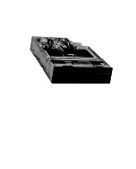
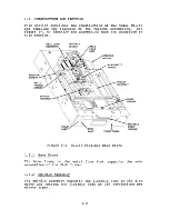
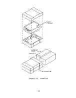
Page 22: ...PLASTIC FILM COVER Figure 2 1 Unpacking 2 2 ...

Page 23: ... installed in any clean rela tively dust free environment with an ambient temperature of 50 F to 113 F 10 C to 45 C and relative humidity of 20 to 80 The maximum stray magnetic field is 4000 Amperes per meter Aim Typical hea t diss ipation is 22 3 Ki logram Calor ies per Hour Kcal h 23 3 Kcal h with VFO 2 3 2 Space and Weight Data The unit should be mounted to provide space for cabling and servici...

Page 24: ... Model FDl165 Physical Dimensions 1 1 1111 DOOR HANDLE J Figure 2 3 111 11 1 STEPPING MOTOR SPINDLE MOTOR Vertical Installation COLLET ASSEMBLY SPINDLE MOTOR STEPPING MOTOR Figure 2 4 Horizontal Installation 2 4 ...

Page 25: ...o _I 0 8 in I I 20mm I f 41n i 10 mm A One Disk Drive COUPING BRACKET 0 8 in 20mm 0 4 i 7 1 I f__ 10 mm I B Two or Four Disk Drives NOTE AIR FLOW SHOWN BY BROKEN LINES PASSES THROUGH DISK DRIVES THROUGH HOLES IN THE COUPLING BRACKET Figure 2 6 Air Flow Requirements for Natural Air Cooling 2 5 ...

Page 26: ...al Current 0 75 A 0 8 A 0 9 A Opera ting wO VFO w VFO Starting Current 0 9 A 0 8 A 0 9 A wO VFO w VFO Ripple Vol tage Not greater Not greater than 400 mV pp than 70 mV pp Transient Response 200 ms Time Not including voltage spikes 2 4 2 Power Connector The power supply connects to the PCB of the Model FDl165 through a 7 pin connector Table 2 2 lists the part numbers for the power connector Figure ...

Page 27: ...3 Power Connector Pin Assignments The pin assignments for the power connector are shown in Figure 2 8 SIGNAL NAME PIN NUMBER 24 VDC 1 GROUND 2 DC 5VDC 3 POWER POWER GROUND 4 CONNECTOR SUPPLY 5 6 FG 7 Figure 2 8 Pin and Line Assignments for the Power Connector 2 7 ...

Page 28: ...h 49 are located on the noncomponent side of the PCB the even numbered contacts 2 through 50 are located on the component side of the PCB see Figure 2 9 Figure 2 10 shows the recommended interface connector Table 2 3 lists the contact assignments for the connector COMPONENT SIDE OF PCB 2 4 5 0 49 NONCOMPONENT SIDE OF PCB Figure 2 9 Contact Arrangement for Edge Connector INTERFACE CONNECTOR PCB Fig...

Page 29: ...P WRITE DATA WRITE GATE TRACK 00 WRITE PROTECT READ DATA MFM WINDOW CONTACT NUMBER 2 4 6 8 10 12 14 16 18 20 22 24 26 28 30 32 34 36 38 40 42 44 46 48 50 Enabled by jumpers Signals used only when VFO option is installed 2 6 TERMINATOR RESISTORS The Model FDl165 is shipped with terminator resistor arrays RNI and RN2 installed as shown in Figure 2 11 Do not re move these resistors when only a single...

Page 30: ... I ID 2 BS 1 1 BU 2 T3 E I T2 RV1 RV 2 RN 2 I _ _ I 1E J 2 Hl RV 3 DX1 DX2 DX3 DX4 1 3 1 3 1 3 1 3 CJ OX PLUG CJ CJ 2 4 2 4 2 4 2 4 POS1 POS2 RX HL DR PR DL DH 1Ej 2 1 Ej 2 BU JUMPERS POS1 POS2 BS FR 2 E3 1 2Ej 1 JUMPERS POS1 POS2 US RD PINS SOLDER TYPE 2 1 2 1 Figure 2 11 Terminator Resistors and Jumper Locations on the PCB 2 10 ...

Page 31: ...TROLLER TR TR TR TR DC CABLES I A PARALLEL CONFIGURATION FOUR DRIVES MAXIMUM A SIGNAL CABLES V V V FLEXIBLE DISK FLEXIBLE FLEXIBLE FLEXIBLE FLEXIBLE DRIVE DISK DRIVE DISK DRIVE DISK DRIVE DISK DRIVE CONTROLLER DX1 DX2 DX3 DX4 TR DC CABLES I B SERIES CONFIGURATION TR TERMINATOR RESISTOR Figure 2 12 Parallel and Series Configurations 2 11 ...

Page 32: ... For an explanation of the signals that are affected by changing the option selection jumpers see Chapter 3 2 8 1 Head Load Jumper HL A Head Load signal from the controller initiates head load action when the HL jumper is in the HLl position When the jumper is in the HL2 position a Drive Select signal from the controller initiates head load action The FDl165 is supplied with HLl selected 2 8 2 Rad...

Page 33: ...ock jumpers which are used in different combinations with the In Use signal to deter mine the door lock condition This section describes the functions of the door lock jumpers 2 8 6 1 DR Jumper When DRI is sel ected the Ready signal from the con troller enables the door lock function see Table 2 4 When DR2 is selected the door locks function is independent of the Ready signal The disk drive is sup...

Page 34: ... disable the In Use signal solder Pin 2 to the center pin The disk drive is supplied with USI connected to the center pin 2 8 8 Read Data Pins RD The read da ta pi ns are solder type connec tor s To enable the Read Da ta signal solder Pin 1 to the cen ter pin To enable the Standardized Read Data signal for the VFO op tion solder Pin 2 to the center pin The Model FDl165 is supplied with ROI connect...

Page 35: ...mper 2 9 OPERATING THE FDl165 This section describes inserting a flexible disk into the disk drive and removing a flexible disk from the disk drive 2 9 1 Inserting a Flexible Disk Use this procedure to insert a flexible disk into the disk drive a Turn on the dc power supply b Insert a flexible disk into the FDl165 until the flexible disk locks in place and close the door see Figure 2 13 FLEXIBLE D...

Page 36: ...ng the Door and Removing the Flexible Disk 2 10 DISPLAY LAMPS The FDl165 has two display lamps on the front panel the ready lamp and the busy lamp 2 10 1 Ready Lamp The ready lamp shows that the FDl165 is ready for use The lamp is lit when the following conditions are met Dc power is supplied A flexible disk is loaded and the door is closed The flexible disk is rotating at 70 or better of the pres...

Page 37: ...2 10 2 Busy LamE The busy lamp indicates that the disk drive is selected in use or that the read write heads are loaded depending on the position of the BU BS jumpers see Section 2 8 9 2 17 ...

Page 38: ......

Page 39: ...notch The read write head is located on the track 00 of the flexible disk An index sensor provides a time reference by genera ting a pulse for each rotation of the flexible disk After the flexible disk reaches 70 of its prescribed speed and the Index pulse is detected four times a Ready signal is sent to the controller The FDl165 is ready about 700 ms after the door is closed After the disk drive ...

Page 40: ...the disk drive All driver circuits are the open collector type of SN7438 Integrated Circuit Ie The SN7438 driver circuits sink a maximum current of 40 rnA at the low level Each receiver circuit receives a drive signal from the con troller The receiver circuits are Large Scale Integration LSI gate circuits that terminate with l50 ohm resistors Li nes recei ving at high speeds use a Schmi tt tr igge...

Page 41: ...VFO SYNC 24 DRIVE SELECT 1 26 DRIVE SELECT 2 28 DRIVE SELECT 3 30 DRIVE SELECT 4 32 DIRECTION SELECT 34 STEP 36 WRITE DATA 38 WRITE GATE 40 _ TRACK 00 42 _ WR ITE PROTECT 44 READ DATA 46 MFM4 48 WINDOW 50 SIGNALS USED ONLY WHEN VFO OPTION IS INSTALLED Figure 3 2 Interface Lines 3 3 INPUT SIGNALS This section describes the input signals that are carried on the interface lines for the Model FDl165 3...

Page 42: ...ck STP U u 1W T 1 u T 3 ms MIN W 1J1S TO 2 5 ms Figure 3 3 Step Signal Timing 3 3 4 Direction Select DIR If the Direction Select signal is High the head moves toward the external tracks If DIR is Low the head moves toward the internal tracks The trailing edge of this sig nal occurs 1 s before the leading edge of the STP signal 3 3 5 Side Select SSL This signal selects the side of the disk that is ...

Page 43: ...gh Figure 3 4 is the WGT timing chart WGT I 1 ERASE SIGNAL I NOTE THE HEAD LOAD SIGNAL CANNOT BE TURNED OFF THE SIDE SELECT SIGNAL CANNOT BE CHANGED AND THE STEP OPERATION CANNOT BE ENABLED DURING THIS INTERVAL Figure 3 4 WGT Timing 3 3 7 Write Data WDT The signals on this line contain the data that is written on the flexible disk The da ta is in Frequency Modula ted FM or in Modified Frequency Mo...

Page 44: ...e status see Section 3 4 5 3 3 10 In Use USE The USE line goes Low to inst uct the disk drive to lock the door see Section 2 8 6 and 2 8 7 3 4 OUTPUT SIGNALS This section describes the output signals of the Model FOIJ 65 3 4 1 Index lOX This signal occurs on the Index Line once for every rotation of the flexible disk Figure 3 6 shows the lOX pulse lOX T 166 7 3 3 ms W 1 TO 3 ms Figure 3 6 Index Si...

Page 45: ...is closed The flexible disk has reached 70 of its prescribed rotational speed and four lDX pulses have been gen erated The flexible disk is single sided and side 0 is de tected 3 4 5 File Unsafe FUS The File Unsafe signal goes Low when an alarm condi tion occurs The low FUS disables write operations and is reset to High by a E ile Unsafe Reset signal The line goes Low for any of the following cond...

Page 46: ...00 50 ns T 2 lS T 1 5T 411 1 5T 2T Figure 3 7 Read Data Signal Timing 3 4 7 Write Protect PRT The Write Protect signal goes High when the flexible disk does not have a write protect notch If the flexible disk has a wr i te protect notch the Wr i te Protect signal goes Low A Low Write Protect signal puts the flexible disk in a write protected state 3 4 8 Disk Change DCG When the flexible disk has b...

Page 47: ...n SYC The SYC signal goes Low when read data is synchronized by the VFO circuit 3 5 3 Standardized Read Data SRD The SRD line conveys Standardized Read Data The data is synchronized by the VFO circuit to make it easily and more reliably read 3 5 4 Window WID The controller uses the WID signal to distinguish between clock pulses and data output by phase matching the Window signal with the Standardi...

Page 48: ... Sequence The FDl165 processes valid I O signals 700 ms after the door is closed 3 6 2 Drive Select The disk drive processes valid I O signals 500 ns after the Drive Select line DX goes Low 3 6 3 Step and Track 00 Figure 3 10 shows the required time relationship between the Step signal from the controller and the Track 00 output signal STP U u TRO t T I T 2 5 ms MAX Figure 3 10 Step and Track 00 T...

Page 49: ...TE FOR THE DIRECTION SELECT SIGNAL TO CHANGE THE STEP PULSE INTERVAL MUST BE MORE THAN 18 ms Figure 3 11 Access Timing 3 6 5 Write Figure 3 12 shows the required time relationships of con troller signals during a Write operation SIDE SELECT SSL r 4 ps MAX t 4 IJ S MAX WRITE DATA WDT LI1fl I mr HEAD LOAD HDU r 50 ms MIN STEP STP u uu I 18 ms MINI I I O t II I l00 S MIN 1 NJ WRITE GATE WGTl l I Figu...

Page 50: ...er sig nals during a Read operation HEAD LOAD HDL l 1 50 ms MIN I STEP STP l JUlJr I 18 ms MIN SIDESELECT SSL _ _ __ _ 1 100 s MINI WRITE GATE WGT II READ DATA R DT _ u u u u u u I JJ I I JJ J I JJ J u t i u t i I I I t I I I t I I I t Figure 3 13 Read Timing 3 12 ...

Page 51: ...gn material from around the insertion slot and from the front panel of the disk drive 4 2 MAINTENANCE TOOLS In addition to the standard maintenance tools oscilloscope screwdriver feeler gauge and so on several special main tenance tools see Table 4 1 are required to service the FDl165 Table 4 1 Maintenance Tools TOOL NEC PART NUMBER Disk Drive Tester 134 190336 0 Adjusting Driver 134 190337 0 Alig...

Page 52: ...A 1 134 147109 0 1 134 132355 0 1 134 132358 0 1 134 132357 0 1 l34 147102 002 A 1 134 132361 0 1 134 132341 0 1 134 147097 0 1 134 835102 0 1 4 4 REMOVAL AND REPLACEMENT PROCEDURES This section describes the part removal procedures for the Model FDl165 The replacement procedures are the rever se of the removal procedures unless noted Mechanical adjust ments are included with the removal and repla...

Page 53: ...Remove the four screws that fasten the spring plate and the press plate to the base frame c Remove the collet assembly from the base frame HEAD UN LOAD SPRING SPRING PLATE PRESS PLATE SCREW Figure 4 1 Removing the Collet Assembly Use the following procedure to replace and check the collet assembly a Fi t the collet assembly adj usting J 19 to the new collet assembly then fit the collet assembly to...

Page 54: ...rews d Replace the head unload spr ing The clearance be tween the arm on the head load cam and the head un load spring should be 0 to 008 inches 0 to 0 2 rom see Figure 4 2 SHAFT SPRING PLATE SPINDLE ASSEMBLY COLLET oTO 008 in 0 TO 0 2 mm SPINDLE ASSEMBLY SPRING PLATE HEAD UNLOAD SPRING HEAD UN LOAD CAM Figure 4 2 Replacing the Collet Assembly 4 4 ...

Page 55: ...he head unload spr ing and the spr ing plate is within specifications check the position of the spring plate as follows a Make sure that the head load cam is in the unload position b Insert a flexible disk into the drive until the disk locks in place remove the flexible disk and close the door c Check with a feeler gauge that the clearance between the spring plate and the surface of the base frame...

Page 56: ...he heads c Open the door making sure that the heads unload before the flexible disk pops up d Make sure that the flexible disk does not con tact the heads during ejection 4 4 3 Carriage Assembly Removal and Replacement Use the following procedure to remove the carriage assembly a Remove the PCB b Trace the wiring to the carriage assembly and free the wiring from the plastic clips that secure the w...

Page 57: ... frame and measure the gap at points A and B in Figure 4 5 c Select two spacers to insert into the gaps NOTE Determine the size of the spacers as follows The spacer for gap A is the measured value minus 016 inches 0 4 rom The pacer for gap B is the measured value minus 012 inches 0 3 mm If the measured values are 016 inches 0 4 mm and 012 inches 0 3 mm or less respectively no spacers are needed d ...

Page 58: ...he head load cam assembly and separate the wir ing harness from the clips that fasten it to the base frame c Remove the three screws that secure the head load cam assembly to the base frame d Turn the head load cam to the unload position e Holding the head load cam assembly by the bracket remove it from the base frame by moving it clock wise To remove the head load cam remove the screw that secure...

Page 59: ... PCB ROTARY SOLENOID BASE FRAME t q REFERENCE SURFACE OF THE BASE FRAME o L L_ _L l BRACKET DIVISION HEAD LOAD CAM STEPPING MOTOR Figure 4 7 Installing the Head Load Cam Assembly 4 4 5 Wr ite Protect Sensor and Media In Sensor Removal and Replacement Use the following procedure to remove either sensor a Removing the screw that fastens the sensor to the base frame assembly b Remove the hea t shr in...

Page 60: ... screw touches the rear of the elongated hole in the sensor see Figure 4 9 c Tighten the screw MOVE THE SENSOR IN _ THIS DIRECTION ELONGATED HOLE WRITE PROTECT SENSOR Figure 4 9 Installing the Write Protect or Media In Sensor 4 4 6 Optical Tachometer Sensor Removal and Replacement Use the following procedure to remove the optical tachometer sensor a Remove the collet assembly b Remove the screw th...

Page 61: ...is 008 to 040 inches 0 It 2 to 1 0 rom see Figure 4 10 c Replace the collet assembly d Tighten the screw OPTICAL TACHOMETER SENSOR SLIDE THE SENSOR IN THIS DIRECTION BEFORE REMOVING IT I I APPROXIMATELY 0 2 in 0 5 mm Figure 4 10 Removing and Replacing the Optical Tachometer Sensor 4 4 7 Sensor Cable Assembly LED Assembly and Index Sensor Removal and Replacement The LED assembly and index sensors a...

Page 62: ...nector through the hole in the base frame d Remove the two screws tha t fasten the LED assembly to the base frame e From the PCB side of the disk drive remove the single screw that fastens the index sensor to the base frame LEVER PLATE HINGE SCREW Figure 4 11 Removing the Sensor Cable Assembly 4 12 ...

Page 63: ...hed Use the following procedure to install and adjust the index sensor a Insert the index sensor into the index sensor groove in the base frame b Install the screw that fastens the sensor to the base frame but do not tighten it c Insert the index sensor adjusting pin into the hole in the index sensor d Push the index sensor touches the adjusting see Figure 4 12 so that the adjusting pin surface of...

Page 64: ...asten the LED assembly to the base frame see Figure 4 11 c Remove the adjusting pin d Perform the index alignment adjustment see Section 5 4 3 4 4 8 Removing and Replacing the Carbon Brushes Use the following procedure to remove a carbon brush a Remove the brush stopper see Figure 4 13 b Remove the brush CAP BRUSH STOPPER BRUSH HOLDER Figure 4 13 Removing a Carbon Brush 4 14 ...

Page 65: ...ture Removal Use the following procedure to remove the armature a Remove the PCB b Insert two nonmagnetic screwdrivers between the magnet cap and the motor flange as shown in Figure 4 14 SCFlEWA MUST BE REMOVED I STOPPER SCREW B MUST BE REMOVED A SCREW C LEFT HANDED THREAD ARMATURE MOVE THE FLANGE IN THIS B DIRECTION TO REMOVE THE ARMATURE Figure 4 14 Removing the Armature 4 15 ...

Page 66: ...ew left handed thread and lift the armature up to remove it 4 4 10 Spindle Assembly Removal Use the following procedure to remove the spindle assembly a Remove the armature b Remove the optical tachometer sensor c Turn the spindle until the two holes in the spindle line up with the screws that fasten the spindle assembly to the base frame d Remove the two screws see Figure 4 15 and lift the spindl...

Page 67: ...move the front panel Figure 4 16 Removing the Front Panel 4 4 12 Picker Rod Removal and Replacement To remove the picker rod remove the screw that fastens the picker rod to the handle plate Use the following procedure to replace the picker rod a Install the picker rod do not tighten the screw b Adjust the clearance between the picker rod and the picker rod holder to 0 04 to 0 06 inches 1 to 1 5 ro...

Page 68: ...op Up Assembly Removal and Replacement Use the following procedure to remove the pop up assembly a Remove the lever plate by removing the four screws that secure it to the lever plate hinges b Loosen the pop up assembly by removing the two screws that fasten it to the base frame see Figure 4 18 c Move any wir ing that is in the way and Ii ft the pop up assembly out of the base frame 4 18 ...

Page 69: ...it to the lever plate hinges b Remove the two screws that fasten the guide rail to the frame see Figure 4 18 c Remove the guide rail r r 1 C t I poP uP ASSEMBLY DOOR r t L_ SCREWS Figure 4 18 Removing the Pop Up Assembly and Guide Rail 4 4 15 Checking the Operation of the Pop Up Feature After replacing the picker rod or the pop up assembly check the operation of the pop up feature as follows a Tur...

Page 70: ...6 Door Lock Solenoid Removal and Replacement Use the following procedure to remove the door lock sole noid a Remove the front panel b Remove the two screws that fasten the door lock solenoid and bracket to the base frame c Trace the wire to the door lock solenoid and sep arate the wire from the clips that secure it to the base frame d Unplug the wire of the door lock solenoid at the PCB e Remove t...

Page 71: ...ock lever and tigh ten the screws If even greater adjustment is needed loosen screws A and B see Figure 4 19 move the door lock sole noid and tighten the screws b Make sure that the lock pin protrudes beyond the lock le ler 0 06 006 inches 1 5 rom 0 15 rom see Figure 4 20B Adjust this value by moving the door handle c Wi th th e solenoid acti vated the clearance from the edge of the lock lever to ...

Page 72: ......

Page 73: ... of diagnostic test pins T2 and T3 see Figure 5 1 The FDl165 is sup plied with the test pins open not connected TPII I I I G89G us aiel 2 1 RV1 RV2 I RN 1 I 1 RX 22 FR 1 1 E l DRI 21r l2 DL PRI E tJ 21c J 2 0 H TP I I I I I I 7 13 1019 12 11 18 1 X 3 2 4 2 1 R N 2 ____ 1E J 2 HL SS _ FOR AUTO SEEK AND AUTO TAP TEST T2 T3 JUMPERS T3e 3T2 T3Ej T2 FORAUTOTAPTEST FOR AUTO SEEK TEST Figure 5 1 Location...

Page 74: ...disk drive b Connect diagnostic pin T3 to the center pin c Turn on the power to the disk drive to start the auto seek test 5 1 3 Auto Seek and Auto Tap Test The auto seek and auto tap test performs the auto seek and auto tap functions simultaneously Select the auto seek and auto tap test as follows a Turn off the power to the disk drive b Connect diagnostic pins T2 and T3 to the center pin c Selec...

Page 75: ...th or Index Index signal for single sided flexible disks Write Protect Signal Track 00 Signal Media detect sensor output 5 4 ADJUSTMENTS AND CHECKS USING THE ALIGNMENT FLEXIBLE DISK Table 5 2 lists the adjustments and checks using the NEC Alignment Flexible Disk Part Number 806 944184 0 and in dicates when the adjustments and checks should be performed Table 5 2 Adjustments ADJUSTMENT OR CHECK WHE...

Page 76: ...ture range of 68 to 78 5 F 20 to 26 C 5 4 1 Head Radial Alignment Check or Adjustment Set the oscilloscope to the settings shown in Table 5 3 then perform the head radial alignment as follows Table 5 3 Head Radial Alignment Oscilloscope Settings ITEM SETTING Channel 1 Channel 2 Mode Inputs Input range Test points Tr igger Time base Probes Normal Inverted Add Ac 100 mV division TP8 and TP9 TP7 dual...

Page 77: ...nt Waveform d If the ratio of the lobes of the waveform is not within specifications loosen the two screws that fasten th carriage to the base frame and adjust the carriage position in or out with the adjusting driver see Figure 5 3 e Tighten the screws f Unload the heads step the carriage to track 76 then step it back to track 38 and load the heads for three minutes g Recheck the waveform h If th...

Page 78: ... Azimuth error Set the oscilloscope to the settings in Table 5 4 then use the following procedure to check for Azimuth error Table 5 4 Head Azimuth Oscilloscope Settings ITEM SETTING Channel 1 Normal Channel 2 Inverted Mode Add Inputs Ac Input range 50 mV division Test points TP8 and TP9 Trigger TP7 dual sided TPlO single sided Time base 0 5 ms division Probes xl 5 6 ...

Page 79: ... SPEC IFICATION B AANDC 0 Figure 5 4 Azimuth Waveform 5 4 3 Index Alignment Check or Adjustment Set the oscilloscope to the settings in Table 5 5 then use the following procedure to check or adjust the Index align ment Table 5 5 Index Alignment Oscilloscope Settings ITEM SETTING Channel 1 Normal Channel 2 Inverted Mode Add Inputs Ac Input ra nge 200 mV division Test points TP8 and TP9 Trigger TP7 ...

Page 80: ...mbly and the index assembly have been replaced see Section 5 5 1 INDEX PULSE I 1_ I 200 200JiS Figure 5 5 Index Alignment Waveform 5 5 OTHER ADJUSTMENTS The checks and adjustments in this section do not require the use of the alignment flexible disk 5 5 1 LED Assembly Index Assembly Check and Adjustment If the index sensor and LED assembly are replaced perform the following check in addition to th...

Page 81: ...the following procedure a Repeatedly perform a seek between track 0 and track 7 at a step time of 3 ms to 5 ms b Check that the Track 00 signal occurs within 2 0 ms to 2 5 rns of the Step signal to track 00 see Figure 5 7 c If the timing exceeds the specified value loosen the installation sC rew of the 00 track sensor and move it inwards until the signal meets the specifi cation 2 0 to 2 5 ms Make...

Page 82: ... change when the flexible disk is moved d Remove the flexible disk and insert a disk without a write protect notch e Check tha t the vol tage at TPII is more than 3 3 V Move the jacket and make sure that the voltage does not change f If the vol tage changes change the posi tion of the sensor until tbe vol tage does not change when the jacket is moved 5 5 4 Head Load Check Perform this check after ...

Page 83: ... Waveform There are three tr im pots on the PCB of the Model FDl165 RVl and RV2 determine the write current They are adjusted a t the factory and should never be adj usted in the fi eld RV3 determines the speed of the spindle motor This trim pot is adjusted for an index pulse width of 166 6 0 5 ms 5 11 ...

Page 84: ......

Page 85: ...s and washers are described in coded form Quantity contains the number of items per assembly The components of the PCB are listed in a four column format Component Designation contains the reference designation identifying the part o n the PCB and on logic schematic diagrams in alphanumeric order Part Number contains the NEC part number to use when 6rdering spare or replac mentparts Descrip1 ion c...

Page 86: ...OWA POWA 20LWA A type hexagon nut B type hexagon nut Small washer Polished washer Spring washer L CPOMS S CPOMS P CPOMS SL CPOMS PL CPOMS SEMUSU screw see Item e The symbol 0 is replaced by one of the following codes to show the material type that is used Iron Brass Spring Steel I B ST b Nominal diameter in mm c Length in mm Not used for nuts and washers 6 2 ...

Page 87: ... plus spring washer Pan head metric screw with cross groove plus polished washer Pan head metric screw with cross groove plus small washer PL CPOMS SL CPOMS Pan head metric screw with groove plus spr ing washer polished washer Pan head metric screw with groove plus spr ing washer small washer cross plus cross plus Table 6 1 List of Illustrations FIGURE NUMBER TITLE PART NUMBER 6 1 FDl165 Flexible ...

Page 88: ...06 0 805 310026 008 0 805 310003 006 0 805 311103 006 0 805 341126 006 0 805 320003 005 0 DESCRIPTION Spindle Motor Assembly Carbon Brush Brush Stopper Armature Spindle Screw Spindle Assembly SenSor Carriage Assembly Collet Assembly Collet Head Load Assembly includes 12 13 Rotary Solenoid Head Load Cam Pop Up Assembly Guide Rail Sensor Cable Assembly includes LED Assembly and Index Sensor G9NYF PC...

Page 89: ...FDl165 Flexible Disk Drive Figure 6 1 6 5 ...

Page 90: ...3 802 530001 034 0 Inductor TP0410L 331J 2 L4 802 530001 015 0 Inducator TP0410L 330K 1 P2 802 710165 207 0 Connector 171826 7 1 P3 806 927164 826 0 Connector 3493 1 P4 806 927325 216 0 Connector 65625 216 1 ASSEMBLY OR LOCATION 01 02 06 07 03 04 05 08 09 011 010 012 013 R1 R4 R12 R13 R19 R2 R3 R5 R6 R7 R10 R15 R11 R23 R14 R16 R17 R18 R20 R21 R27 R22 R25 R36 R24 R26 R28 R29 R30 R31 R32 R33 R34 R35...

Page 91: ...o o o o View AA Figure 6 2 G9NYF PCB Assembly 6 7 ...

Page 92: ......

Page 93: ...CHAPTER 7 SCHEMATIC This chapter contains the schematic drawings for the G9NYF PCB 7 1 2 ...

Page 94: ......

Page 95: ...RYl 19 6 4 7 IXIO HlOO IXOO WEND 45 3 DOPO WSLt 412 REIIO EGOO 48 ClKI EG10 41 PlZl WDFl 25 DlHD RGTl 43 PRIO SWFl J9 DRHO PH10 13 DLSO PH20 14 DRlO PHJO 15 SDHl PH40 16 MlNl DlKO FLSl 24 DSXl 2 3H SF WGTD l SF RM i 10K 6 11 1 1 lO L b USED I2l SC r 1 I 2 1 L 110 USE I L __I SF lson lC 74LSl4PC t I I 9 1 8 IC 74LSI4PC t 1 1 10 1 411 1 lWCl 4 DIRECTION PRTD 31 TROl 3 IX10 3 IXOO 3 MINl 3 REIIOI 2 C...

Page 96: ......

Page 97: ...P14 31 13 DBI 3Z 14 DB2 P15 P16 33 15 DB3 16 P17 34 DB4 PZO Z1 tiRO 17 DB5 PZl ZZ MEllO 18 DB6 PZZ Z3 3 19 DB1 PZ3 24 P24 35 INT 36 PZ5 SS PZ6 37 EA PZ1 38 T1 TO 1 PROG Z5 iiii 8 PS EN 9 WR 10 ALE 11 5F Xll1A I R16 18K SF DIRO 1 II i TROI 3 II _ RIX1 1 11 MINI 3 11 _ _4 TACO 3111 _ X l l A I HLDO 1 II CLROi H D r 1 I HLDO l 1 i rI 1 _11 1 TP i ell 1 I l_ J DSXO 1 1 llS EO 1 I to HLDN 1 134 110390 ...

Page 98: ......

Page 99: ...o 9 8 5G RN3 2 56O Q TPll I IIIN1 1 5V 220Q RN4 5 r 4 r i PRTO 1 r b t lQ DTR01 1 I lC I t TX10ll 1 ___1 t lO 4 OTXOO 1 00 TRACK SENSOR i lWI 3 RN4 I Q I 103 I BW 10 4 RN4 n L_ INDEX LED 1 I I I I L _ _ J OPTICAL TACHOMETER SENSOR 1 I I I WRITE PROTECT SENSORI I I I L_ I MEDIA IN SENSOR 134 110390 501 0 FDl165 G9NYF PCB Sheet 3 of 4 7 7 8 ...

Page 100: ......

Page 101: ...5C 30 R3S Rl1 UK 5F 18 20 Z 2002 R312701K 1I SN74LS04N SN7406N Jl2Eo 6 5 i 5C 6 12F 1 1 R7 1 SK2S 63 5 8 2K RJ1 C4 D1 T 1S953 Dl RD36EB I 1 13 LWCl 1 t WDFD l WSL1 1 WEIIO l EGOO 1 EGID 1 SN7401II SWF1l11 1 1 3 5C 12 14f22r Tlj321 J Sf j rn 12F RGTI 1 1 5E 3300pF b 4 r9 l 1 2 9 1K C8 r 74LS74 5 1__ _ I RA3 10K ri 1 6 12 B L 2 7 I J I J f L LtJ 7lir q j f SN 74 LS5 lN t ly9 3 jR2O fT1 L r 1 1 6K I ...

Page 102: ......

Page 103: ...TS FORM Document FDl165 Flexible Disk Drive Maintenance Manual Document No 819 000090 2001 Please suggest improvements to this manual I as I rn Please list any errors in this manual Specify by page as CD il From Name Title Company Address _ Date ...

Page 104: ... REPLY CARD FIRST CLASS PERMIT NO 386 LEXINGTON MA POSTAGE WILL BE PAID BY ADDRESSEE NEe Information Systems Inc Dept Publications 5 Militia Drive Lexington MA 02173 FOLD HERE Seal or tape all edges for mailing do not use staples NO POSTAGE NECESSARY IF MAILED IN THE UNITED STATES ...

Reviews: