CHAPTER 2 NAMES AND FUNCTIONS OF PARTS
User’s Manual U11595EJ5V0UM
28
2.2
Clock Setting
Remark
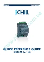
JP2 in the pod is factory-set as shown on the right
(The numbers 1, 2, 7, 8 are the jumper pin numbers
printed on the board).
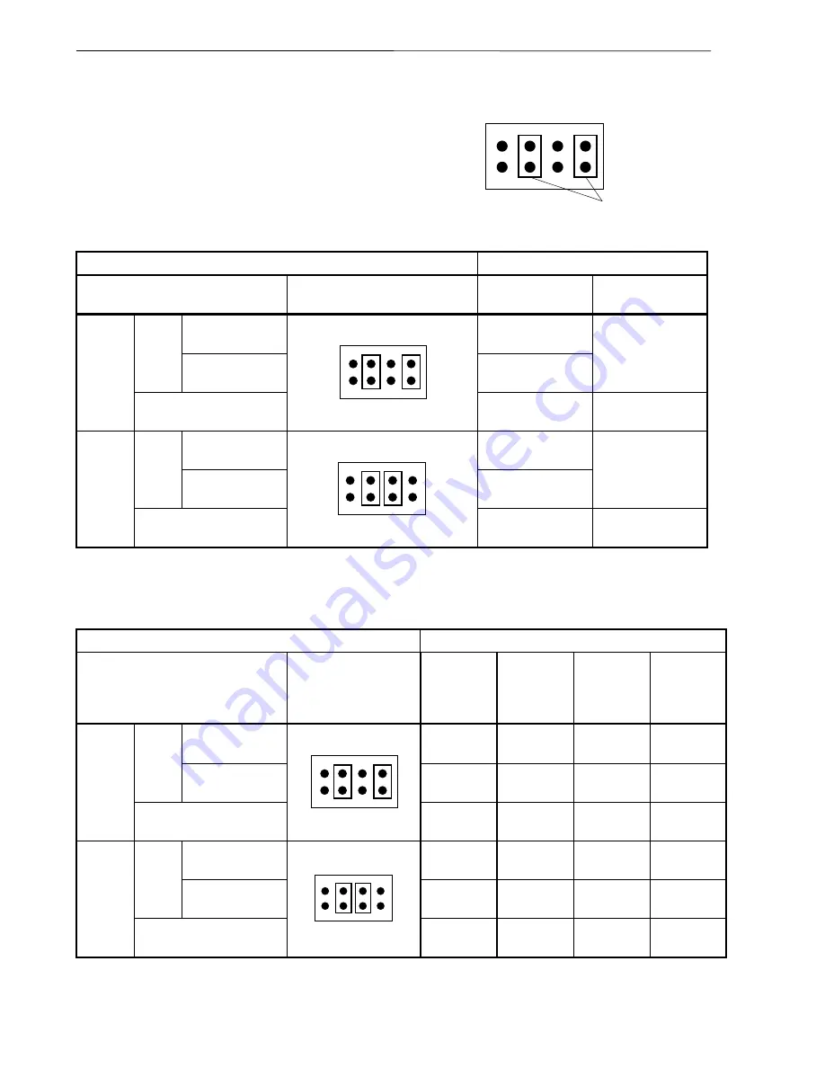
2.2.1 When IE-703002-MC is used alone
When IE-703002-MC is used to develop V852 application system
Clock Supply Source Setting
Clock Mode Setting
Clock Supply Method
Pod JP2 Setting
Pod SW1 Setting
(PLLSEL Setting)
Pod SW2 Setting
(CKSEL Setting)
×
5 multiplication
(input clock
×
5)
ON
PLL
mode
×
1 multiplication
(input clock
×
1)
OFF
OFF
Internal
clock
Direct mode
(input clock
×
1/2)
7
8
1
2
don’t care
ON
×
5 multiplication
(input clock
×
5)
ON
PLL
mode
×
1 multiplication
(input clock
×
1)
OFF
OFF
Target
clock
Direct mode
(input clock
×
1/2)
7
8
1
2
don’t care
ON
2.2.2 When IE-703002-MC is used connected to target system
When IE-703002-MC is used to develop V852 application system
Clock Supply Source Setting
Clock Mode Setting
Clock Supply Method
Pod JP2 Setting
Pod SW1
Setting
(PLLSEL
Setting)
Pod SW2
Setting
(CKSEL
Setting)
Pod SW2
Setting
(CKSEL
Setting)
CKSEL
Setting of
Target
System
×
5 multiplication
(input clock
×
5)
ON
High level
OFF
Low level
PLL
mode
×
1 multiplication
(input clock
×
1)
OFF
Low level
OFF
Low level
Internal
clock
Direct mode
(Input clock
×
1/2)
7
8
1
2
don’t care
don’t care
ON
High level
×
5 multiplication
(input clock
×
5)
ON
High level
OFF
Low level
PLL
mode
×
1 multiplication
(input clock
×
1)
OFF
Low level
OFF
Low level
Target
clock
Direct mode
(Input clock
×
1/2)
7
8
1
2
don’t care
don’t care
ON
High level
7
8
1
2
Jumper contact