


CHAPTER 3 CONNECTION OF PARTS
User’s Manual U11595EJ5V0UM
34
(b) IE-70000-PC-IF-C
The I/O addresses are set with DIP switch 1 (SW1) and DIP switch 2 (SW2) on the PC interface board.
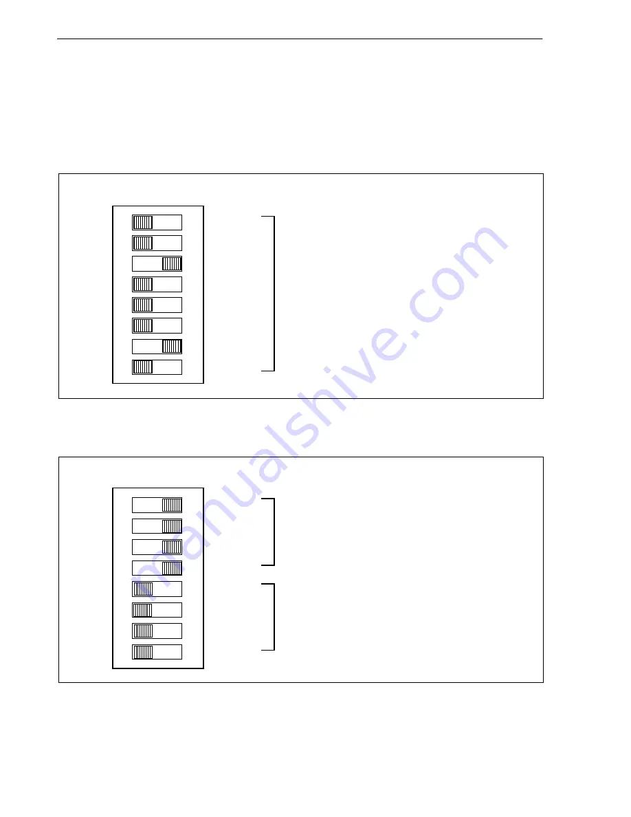
SW1 and SW2 are setting switches of the handshake bus address. Set switches No. 1 to No. 8 of SW1 as
shown in Figure 3-3 and switches No. 1 to No. 4 of SW2 as shown in Figure 3-4 (set to address 022
×
H).
Set INT JP to NO_USE and WAIT JP to the short between 2 and 3.
Figure 3-3. Setting of DIP Switch 1 (SW1) (IE-70000-PC-IF-C)
Figure 3-4. Setting of DIP Switch 2 (SW2) (IE-70000-PC-IF-C)
Allocate handshake bus for I/O addresses of PC (set bits
15 to 12 of I/O address of PC).
Reserved (switches No.5 to 8 are fixed as shown)
ON
8
7
6
5
4
3
2
1
A11
A10
A9
A8
A6
A5
A4
A7
SW1
ON
8
7
6
5
4
3
2
1
A15
A14
A13
A12
SW2
Allocate handshake bus for I/O addresses of PC (set bits
11 to 4 of I/O address of PC).


