User’s Manual U11595EJ5V0UM
44
CHAPTER 5 OPTION BOARD
The IE-703002-MC can be used as an in-circuit emulator for developing systems using V853 and V850/Sxx
products (but not the V852) by connecting an option board (sold separately).
Execute the following sequence if the IE-703002-MC is used as an in-circuit emulator for V853 and V850/Sxx
products (not V852).
(1) Remove the covers (upper side and lower side) of the pod of the IE-703002-MC.
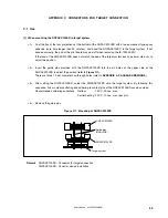
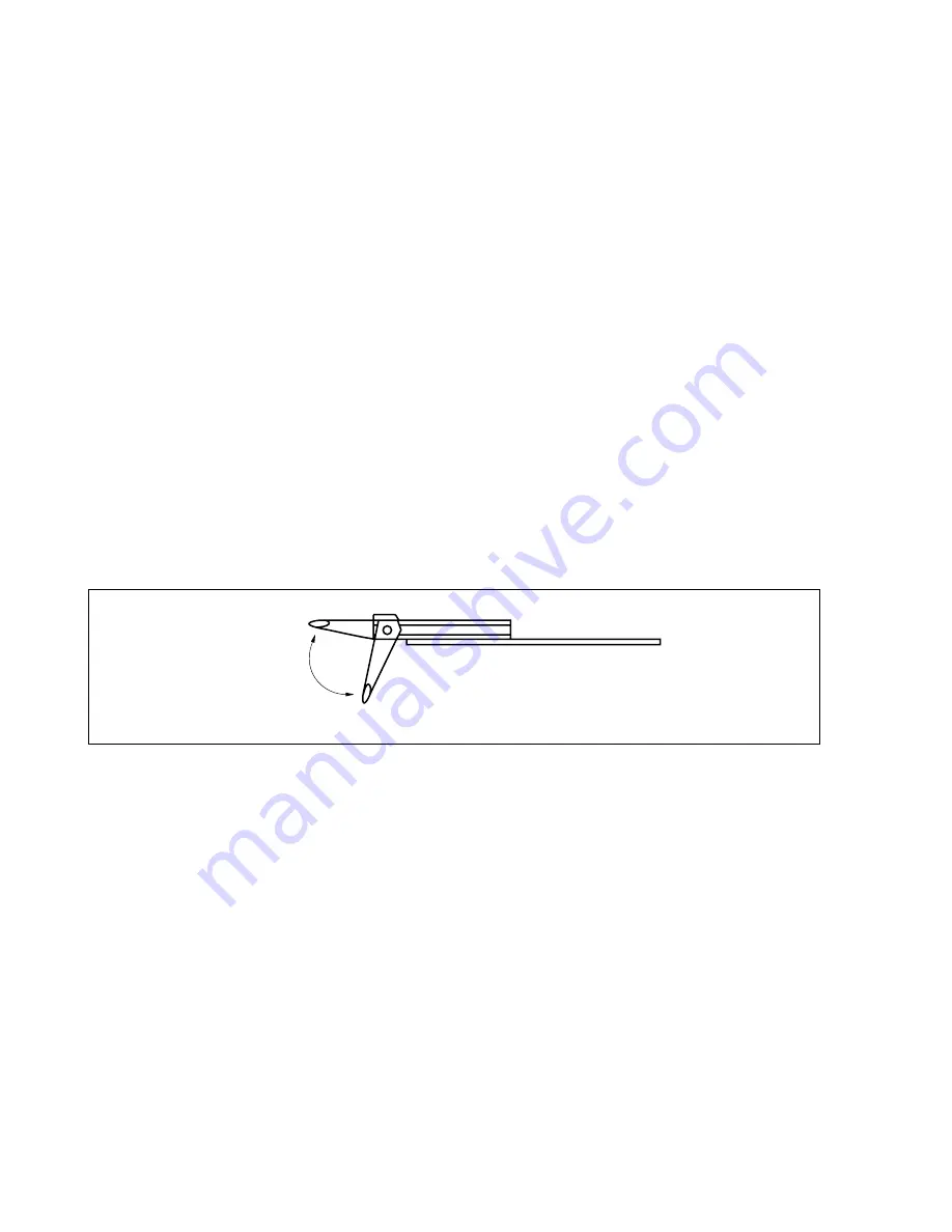
(2) Set the option board PGA socket lever to the OPEN position as shown in Figure 5-1.
(3) Connect the option board to the PGA socket at the back of the pod. When connecting, position the IE-703002-
MC and the option board horizontally.
(4) Set the option board PGA socket lever to the CLOSE position as shown in Figure 5-1.
(5) Set the jumpers (JP1 to JP4) and switches (SW1 and SW2). Open JP1 (remove jumper contact. Attach the
removed jumper contact to one of the jumper pins to avoid losing it). Set JP2 to JP4, and SW1 and SW2
depending on the use.
(6) Secure the pod covers (upper and lower) to the option board with the provided plastic screws.
(7) Secure the end of the pod cover (upper) with nylon rivets.
Remark
For details, refer to the in-circuit emulator user’s manual for the V853 or V850/Sxx product used.
Figure 5-1. Option Board PGA Socket Lever
CLOSE
OPEN


