CHAPTER 2 NAME AND FUNCTION OF COMPONENTS
22
2.3
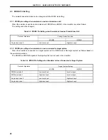
MODE Pin Setting
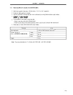
The emulator operation mode can be changed with the MODE pin setting.
2.3.1 MODE pin setting when emulator is used as stand-alone unit
When the emulator is used as a stand-alone unit, MODE0 and MODE1 in the emulator are set as follows.
The setting cannot be changed.
Table 2-3. MODE Pin Setting when Emulator is Used as Stand-Alone Unit
Settings Inside Emulator
Emulator Operation
MODE0
MODE1
Single-chip mode 0
Low-level input
High-level input
2.3.2 MODE pin setting when emulator is used connected to target system
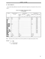
When the emulator is connected to a target system, set the MODE pins of the target system as follows based on
the emulator operations.
The MODE2 and MODE3 signals in the target system are not used in the emulator.
Table 2-4. MODE Pin Setting when Emulator is Used Connected to Target System
Target System Setting
Emulator Operation
MODE0
MODE1
ROM-less mode 0
Low-level input
Low-level input
ROM-less mode 1
High-level input
Low-level input
Single-chip mode 0
Low-level input
High-level input
Single-chip mode 1
High-level input
High-level input
Summary of Contents for IE-703102-MC-EM1
Page 2: ...2 MEMO ...
Page 10: ...10 MEMO ...
Page 24: ...24 MEMO ...
Page 26: ...26 MEMO ...
Page 34: ...34 MEMO ...
Page 40: ...40 MEMO ...
Page 46: ...46 MEMO ...
Page 48: ...48 MEMO ...


