IWSTAND
Assembly Instructions
4
© NEC Display Solutions of America. All Rights Reserved, 2007
Frame Assembly
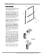
The first step in the assembly process is
to identify and place all the frame mem-
bers on the floor as shown.
Please note that all of the frame mem-
bers have been color coded for easy
identification. See
Parts List
for color
code and identification numbers. A
Color
Dot
has been placed on the sur-
face that is considered the front of the
stand or relating to special assembly
procedure in these instructions.
The details pertaining to how the frame
members fit together is illustrated in
Detail A
. Always slide the rail slot into
the retaining clip as shown.
Frame member 5 and 6 have access
holes located in the slot.
Make sure
that the hole lines up with the screw
head
. You will be able to see the screw
head by looking through the access
hole. When the two are aligned, place
hex key (allen wrench) into hole and
tighten screw.
Assemble as shown: first assembling
lower moving frame rail (
5 - Orange
)
and then upper moving frame rail (
6 -
Dark Blue
) to sliding frame verticals (
2
- Black and 3 - Light Blue
).
The pull
pins are on the back side. Also, note
that the lower moving frame rail ( 5 )
has two large holes on one side. This
is the backside. The upper rail (
6
)
has four holes on one side. This is the
front side of the rail.
Attach this rail
second, positioned as shown.
Finally attaching the lower horizontal
member (
4 - Red
) to frame verticals
(
2 and 3
) with a screw (
14
) and
6
3
5
2
4
15
14
Detail A


