Release 6.0
11
User Guide
Figure 8-10: Removing the Controller Cover...............................................................................................257
Figure 8-11: Removing the Battery..............................................................................................................258
Figure 8-12: Removing the DIMMs..............................................................................................................260
Figure 8-13: Removing the Flash Memory ASSY........................................................................................262
Figure 9-1:
Getting Started - Host Information Collection..........................................................................312
Figure C-1: Unit with NF53x1-xFxx (10Gbps iSCSI 2port Controllers) ......................................................321
Figure C-2: Unit with NF53x1-xFxx (1Gbps iSCSI 2port Controllers) ........................................................321
Figure C-3: Configuration Example............................................................................................................322
Figure C-4: Microsoft iSCSI (1) Dialog Box................................................................................................323
Figure C-5: Microsoft iSCSI (2) Screen......................................................................................................323
Figure C-6: Software Update Installation Wizard Screen (1) .....................................................................324
Figure C-7: Software Update Installation Wizard Screen (2) .....................................................................325
Figure C-8: Software Update Installation Wizard Screen (3) .....................................................................326
Figure C-9: Software Update Installation Wizard Screen (4) .....................................................................327
Figure C-10: Software Update Installation Wizard Screen (5) .....................................................................328
Figure C-11: Application Server Desktop Screen ........................................................................................328
Figure C-12: iSCSI Initiator Properties (General Tab) Screen .....................................................................329
Figure C-13: iSCSI Initiator Properties (General Tab) Screen .....................................................................330
Figure C-14: CHAP Secret Input Window ....................................................................................................331
Figure C-15: iSCSI Initiator Properties (Discovery Tab) Screen ..................................................................332
Figure C-16: Add Target Portal Screen........................................................................................................332
Figure C-17: Authentication Error Screen ....................................................................................................333
Figure C-18: iSCSI Initiator Properties (Discovery Tab) Screen ..................................................................333
Figure C-19: iSCSI Initiator Properties (Discovery Tab) Screen ..................................................................334
Figure C-20: iSNS Server Add Screen.........................................................................................................334
Figure C-21: iSCSI Initiator Properties (Discovery Tab) Screen ..................................................................335
Figure C-22: iSCSI Initiator Properties (General Tab) Screen .....................................................................336
Figure C-23: iSCSI Setup Tool - Log on to the Target .................................................................................338
Summary of Contents for M100
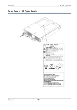
Page 25: ...Release 6 0 25 User Guide About Warning Labels Power Supply AC Power Supply ...
Page 27: ...Release 6 0 27 User Guide About Warning Labels Battery ...
Page 29: ...Release 6 0 29 User Guide About Warning Labels Power Cable AC Power Supply ...
Page 40: ...Release 6 0 40 User Guide Chapter 1 Overview 1 2 1 4 Controller CONT ...
Page 48: ...Release 6 0 48 User Guide Chapter 1 Overview 1 2 3 3 Controller CONT ...
Page 260: ...Release 6 0 260 User Guide Chapter 8 Installing Optional Parts Figure 8 12 Removing the DIMMs ...
Page 459: ...NEC Corporation 7 1 Shiba 5 chome Minato ku Tokyo 108 8001 Japan URL http www necstorage com ...


