Release 6.0
273
User Guide
Chapter 10 Troubleshooting
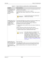
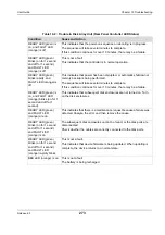
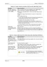
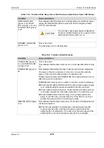
Table 10-2: Trouble in Disk Array Unit (Rear Panel Controller LED Status)
Condition
Cause and Action
READY LED (green) is
on, and FAULT LED
(orange) is off
This indicates that the power-on sequence or rebooting is in progress.
The sequence will take several minutes to complete.
If this condition continues for over 10 minutes, there may be a failure.
READY LED (green)
blinks (on for 1 second
and off for 1 second),
and FAULT LED
(orange) is off
This is not a fault.
This indicates that the controller is in normal operation.
READY LED (green)
blinks rapidly, and
FAULT LED (orange) is
off
This indicates that power has been disrupted, or automatic shutdown or
memory backup is being performed.
The sequence will take several minutes to complete.
If this condition continues for over 10 minutes, there may be a failure.
READY LED (green) is
on, and FAULT LED
(orange) blinks (on for 1
second and off for 1
second)
This indicates that subsequent disk enclosures are not turned on. Turn
on the disk enclosures.
READY LED (green)
and FAULT LED
(orange) are on
This indicates that there is a maintenance request because a failure was
detected. Analyze the error and then remove the cause.
READY LED (green)
blinks (on for 1 second
and off for 1 second),
and FAULT LED
(orange) is on
The subsequent disk enclosures cannot be found, or the disk ports are
disconnected.
Check whether the cables are correctly connected to the disk ports.
READY LED (green)
blinks (on for 1 second
and off for 1 second),
and FAULT LED
(orange) rapidly blinks
This is not a fault.
This indicates that device firmware is being updated. When updating is
complete, the device returns to a normal state.
BBU LED (orange) is on
This is not a fault.
The battery is being recharged.
Summary of Contents for M100
Page 25: ...Release 6 0 25 User Guide About Warning Labels Power Supply AC Power Supply ...
Page 27: ...Release 6 0 27 User Guide About Warning Labels Battery ...
Page 29: ...Release 6 0 29 User Guide About Warning Labels Power Cable AC Power Supply ...
Page 40: ...Release 6 0 40 User Guide Chapter 1 Overview 1 2 1 4 Controller CONT ...
Page 48: ...Release 6 0 48 User Guide Chapter 1 Overview 1 2 3 3 Controller CONT ...
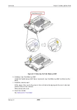
Page 260: ...Release 6 0 260 User Guide Chapter 8 Installing Optional Parts Figure 8 12 Removing the DIMMs ...
Page 459: ...NEC Corporation 7 1 Shiba 5 chome Minato ku Tokyo 108 8001 Japan URL http www necstorage com ...


