2-10 Setting Up the System
Rear View
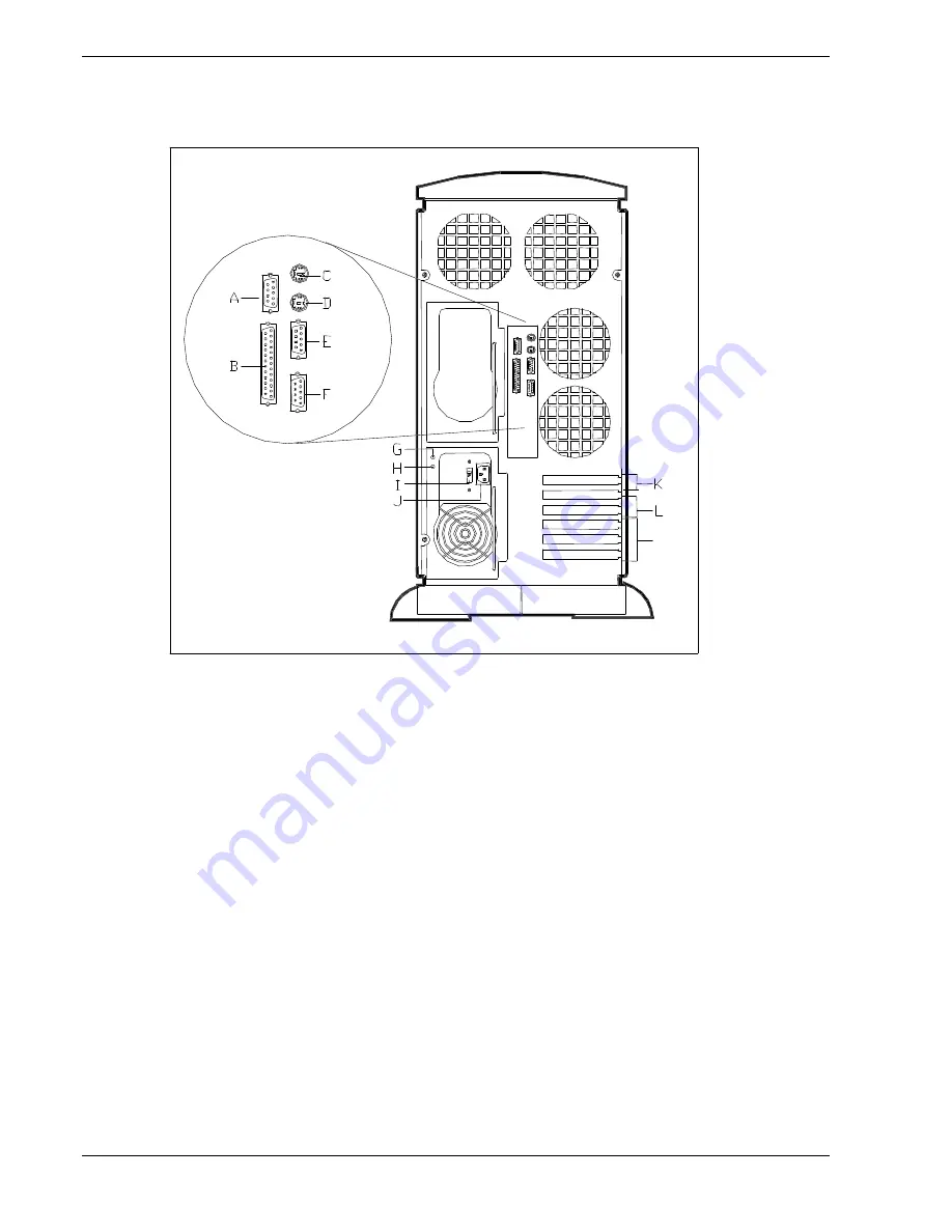
This figure shows the location of the following rear system features and controls.
M
Figure 2-6 Rear Features and Controls
A.
COM1
COM1 serial port 9-pin connector.
B.
Printer
25-pin parallel port connector.
C.
Mouse
PS/2-compatible 6-pin mini-DIN connector.
D.
Keyboard
PS/2-compatible 6-pin mini-DIN connector.
E.
COM2
COM2 serial port 9-pin connector.
F.
VGA
VGA monitor 15-pin connector.
G.
Power Supply Status LED
See Table "Power Supply Status Indicator LEDs (Rear Panel)" that follows.
H
DC Power Status LED
See Table "Power Supply Status Indicator LEDs (Rear Panel)" that follows.
I
Line voltage selector switch
Selects AC input power of 115 VAC or 230 VAC.
J
AC input power connector
Supplies AC power to the power supply.
K.
PCI slot
One PCI add-in board slot locations.
L.
Combo PCI/ISA slot
One PCI or ISA slot location.
M.
ISA slots
Three ISA add-in board slot locations.
Summary of Contents for MC2200
Page 1: ... U s e r s G u i d e Server MC2200 ...
Page 2: ...xxx ...
Page 3: ... U s e r s G u i d e Server MC2200 ...
Page 13: ...Using This Guide xi ...
Page 14: ......
Page 26: ...Packard Bell NEC ...
Page 34: ...2 8 Setting Up the System Figure 2 4 Opening the Front Door ...
Page 66: ...Packard Bell NEC ...
Page 96: ...Packard Bell NEC ...
Page 116: ......
Page 117: ...A System Cabling System Cabling Static Precautions Standard Configuration RAID Configuration ...
Page 124: ...Packard Bell NEC ...
Page 125: ...B System Status Hardware Support Information ...
Page 136: ...10 Glossary ...
Page 141: ...xx ...
Page 142: ... 904455 01 ...


