109
User’s Manual U12697EJ3V0UM
CHAPTER 5 PORT FUNCTIONS
5.1 Digital I/O Ports
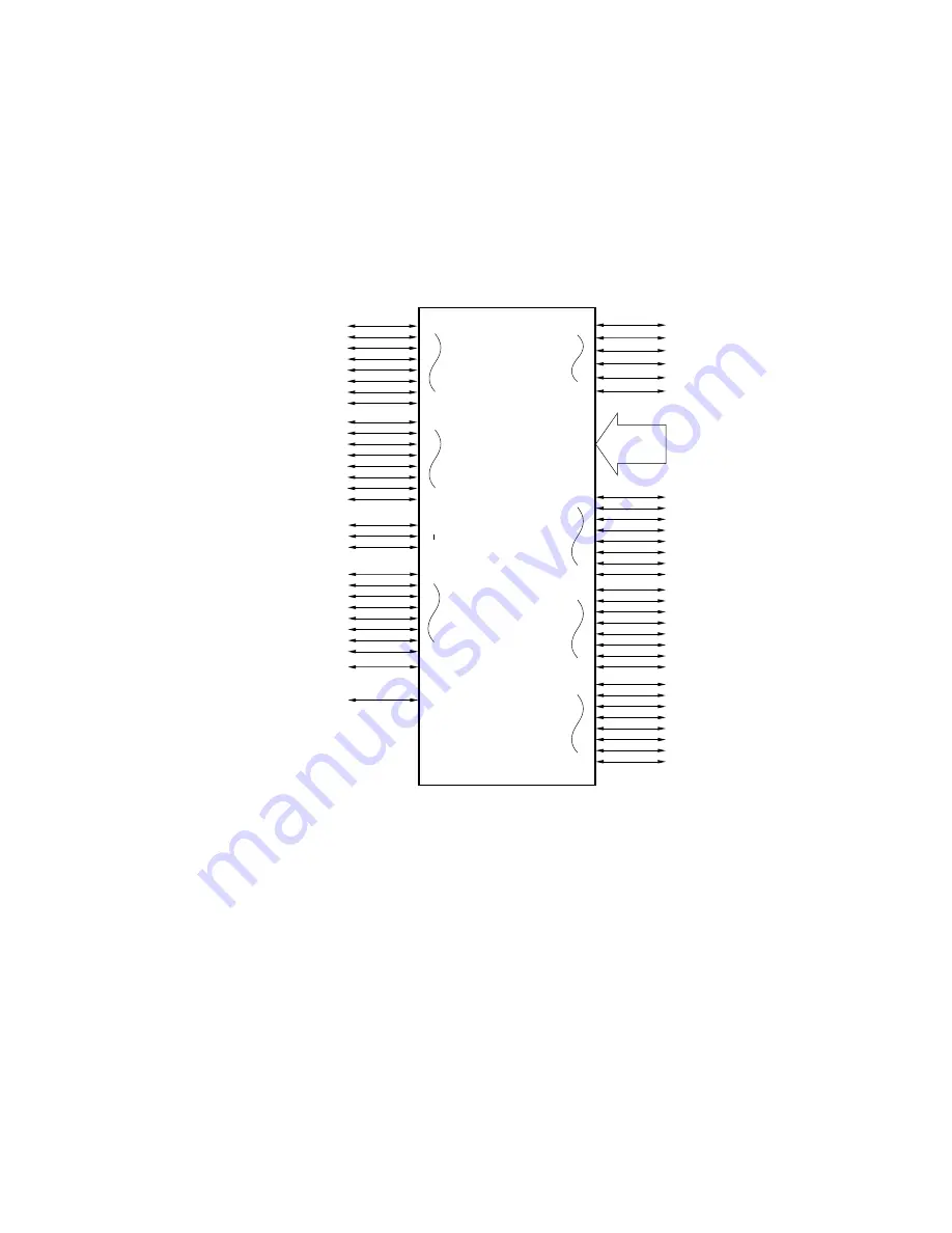
The ports shown in Figure 5-1, which enable a variety of controls, are provided. The function of each port is
described in Table 5-1. On-chip pull-up resistors can be specified for ports 0, 2 to 7, and 12 by software during input.
Figure 5-1. Port Configuration
Port 7
Port 0
Port 2
Port 3
Port 4
Port 1
P70
P72
Port 5
P50
P57
Port 12
P120
P127
Port 13
P130
P131
P00
P05
P10 to P17
P20
P27
P30
P37
P40
P47
8
Port 6
P60
P67


