164
CHAPTER 8 16-BIT TIMER/EVENT COUNTER
User’s Manual U12697EJ3V0UM
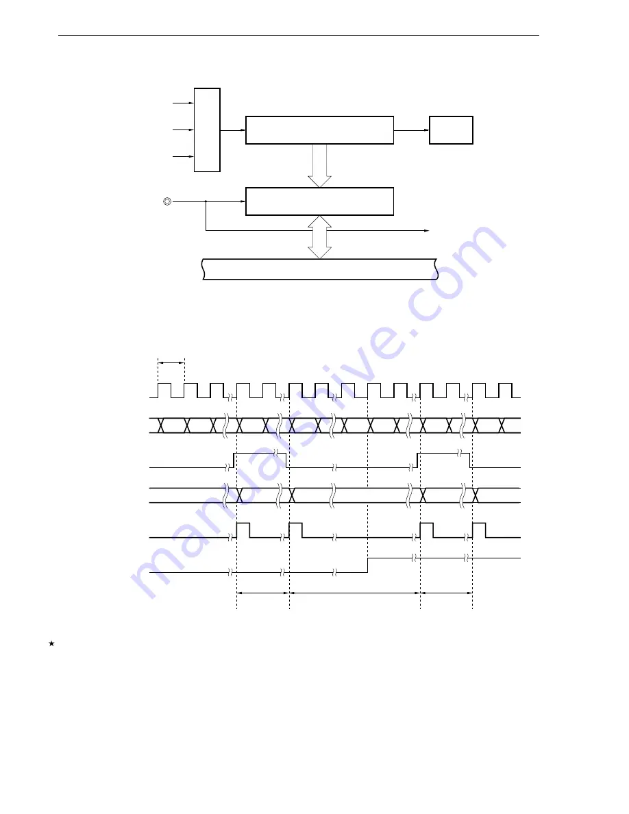
Figure 8-11. Configuration for Pulse Width Measurement with Free-Running Counter
INTTM01
f
XX
/4
f
XX
/16
INTTM3
Selector
16-bit capture/compare register 01
(CR01)
16-bit timer counter 0 (TM0)
OVF0
TI00/P35
Internal bus
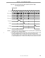
Figure 8-12. Timing of Pulse Width Measurement with Free-Running Counter
and One Capture Register (with Both Edges Specified)
t
(D1 – D0)
×
t
(10000H – D1 + D2)
×
t
(D3 – D2)
×
t
Count clock
0000
0001
D0
D1
0000
D2
D3
TM0 count value
D3
TI00 pin input
Value loaded
to CR01
INTTM01
OVF0
D0
D1
D2
FFFF
Caution For simplication purposes, delay due to noise elimination is not taken into consideration in the
capture operation by TI00 and TI01 pin input and in the interrupt request generation timing in
the above figure. For a more accurate picture, refer to Figure 8-14 CR01 Capture Operation with
Rising Edge Specified.


