173
CHAPTER 8 16-BIT TIMER/EVENT COUNTER
User’s Manual U12697EJ3V0UM
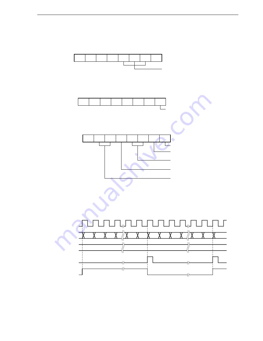
Figure 8-23. Control Register Settings in Square Wave Output Mode
(a) 16-bit timer mode control register 0 (TMC0)
0
0
0
0
TMC03
1
TMC02
1
TMC01
0/1
OVF0
0
TMC0
Clears and starts on match
between TM0 and CR00.
(b) Capture/compare control register 0 (CRC0)
0
0
0
0
0
CRC02
0/1
CRC01
0/1
CRC00
0
CRC0
CR00 as compare register
(c) 16-bit timer output control register 0 (TOC0)
Remark
0/1:
When these bits are reset to 0 or set to 1, the other functions can be used along with the square
wave output function. For details, refer to
Figures 8-2
to
8-4
.
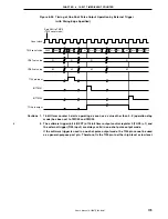
Figure 8-24. Timing of Square Wave Output Operation
0
OSPT
0
OSPE
0
TOC04
0
LVS0
0/1
LVR0
0/1
TOC01
1
TOE0
1
TOC0
Enables TO0 output.
Disables one-shot pulse output.
Does not reverse output on match
between TM0 and CR01.
Specifies initial value of TO0
output F/F.
Reverses output on match
between TM0 and CR00.
0000
0001
N – 1
N
0001 0002
N – 1
N
N
TI00 pin input
TM0 count value
CR00
0000
0000
0002
INTTM00
TO0 pin output


