220
CHAPTER 11 WATCH TIMER
User’s Manual U12697EJ3V0UM
11.2 Configuration
The watch timer includes the following hardware.
Table 11-2. Configuration of Watch Timer
Item
Configuration
Counter
5 bits
×
1
Prescaler
9 bits
×
1
Control register
Watch timer mode control register (WTM)
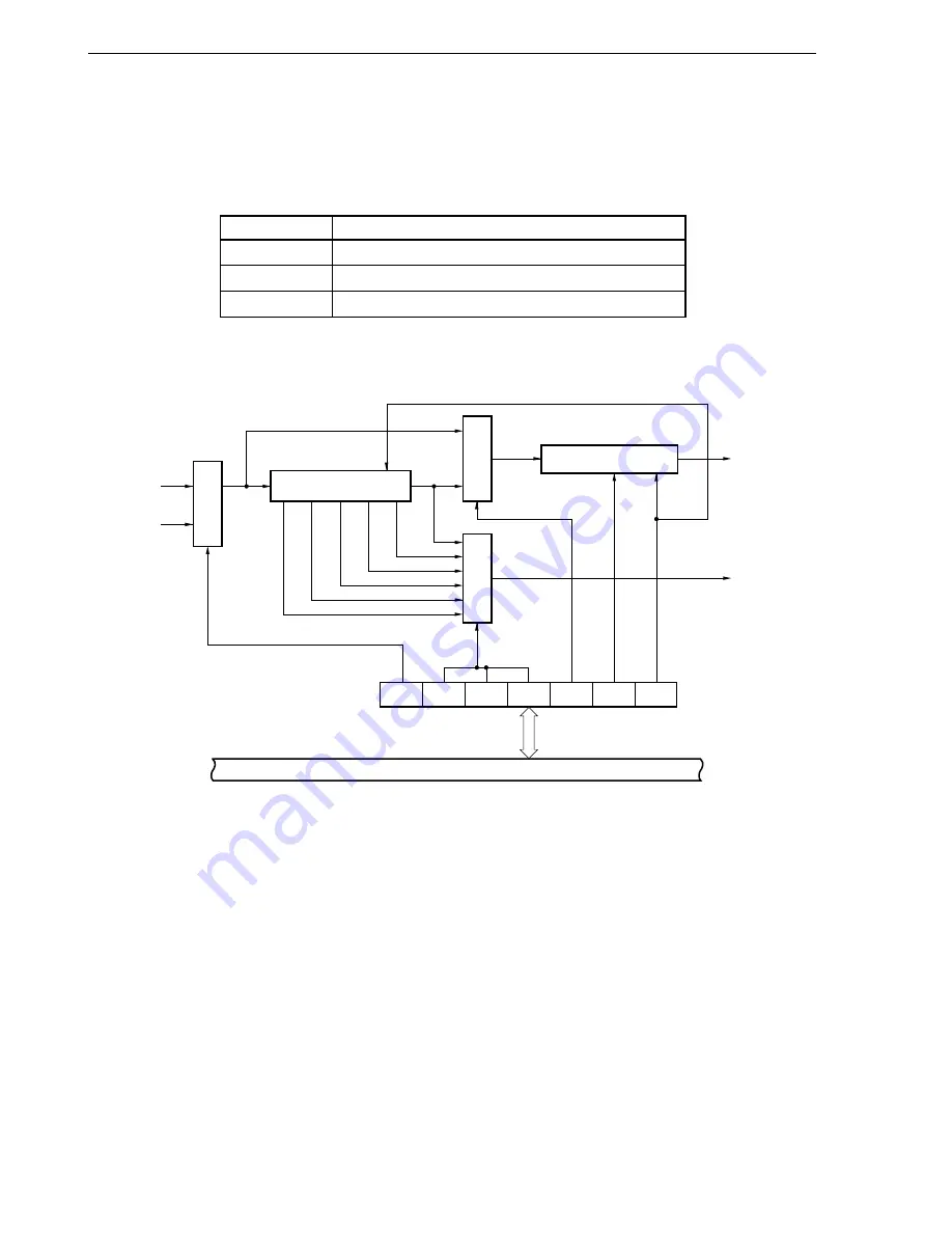
Figure 11-1. Block Diagram of Watch Timer
Selector
Selector
Selector
Internal bus
5-bit counter
9-bit prescaler
f
W
/2
4
f
W
/2
5
f
W
/2
6
f
W
/2
7
f
W
/2
8
f
W
/2
9
f
W
WTM0
INTWT
INTTM3
WTM1
WTM3
WTM4
WTM5
WTM6
WTM7
Watch timer mode
control register (WTM)
f
XX
/2
7
f
XT
Clear
Clear
Remark
f
XX
: Main system clock oscillation frequency
f
XT
: Subsystem clock oscillation frequency
f
W
: Watch timer clock oscillation frequency (f
XX
/2
7
or f
XT
)


