CHAPTER 22 INTERRUPT FUNCTIONS
425
User’s Manual U12697EJ3V0UM
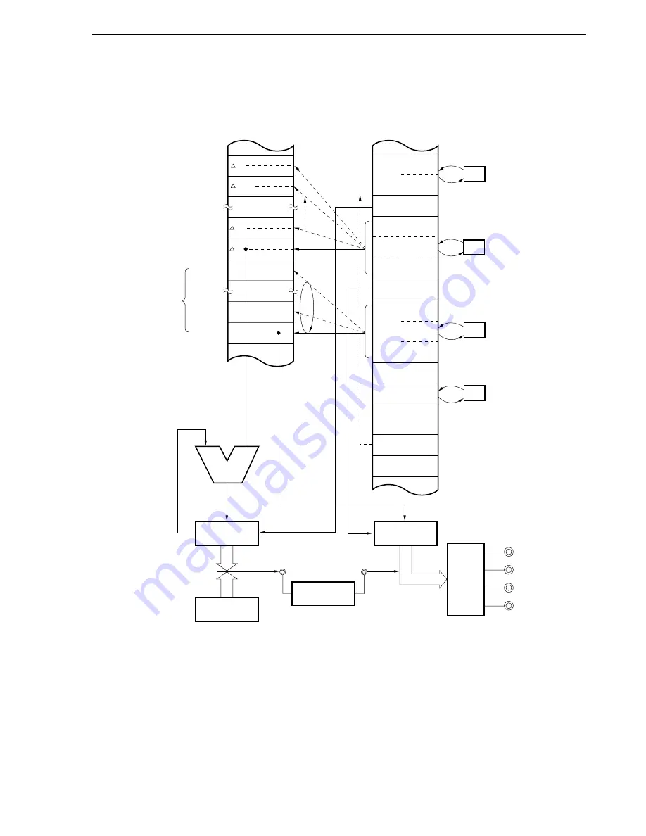
Figure 22-36. Automatic Addition C Ring Control Block Diagram 1
(When Output Timing Varies with 1-2-Phase Excitation)
Remark
Internal RAM addresses in the figure are the values when the LOCATION 0H instruction is executed.
When the LOCATION 0FH instruction is executed, 0F0000H should be added to the values in the figure.
.
.
.
D1
1M memory space
Macro service control word,
macro service channel
(Internal RAM)
16-bit capture/
compare register 00
(CR00)
16-bit timer
counter 0 (TM0)
External
connection
Addition
Buffer register
(RTBL)
Output
latch
P120
P120
P122
P121
P123
0FE5AH
1237FCH
1237FEH
123402H
123007H
Output timing: 123400H
123000H
Output data (8 items)
D7
D0
MSC
01H
00H
12H
MPT
12H
34H
DSFRP
00H
98H
12H
MPD
30H
MR
00H
RC
08H
08H
Channel
pointer
5AH
TSFRP
Mode
register
7FH
Lower 8 bits of CR00 address
Type C, MPT/MPD incremented,
2-byte timer data, automatic addition,
ring control, interrupt request
generation at MSC = 0
Lower 8 bits of RTBL address
To stepper
motor
INTP2
TO0
Match
t256
t
–1
+2
+1
–1
t
t1
..
.


