506
User’s Manual U12697EJ3V0UM
CHAPTER 25 RESET FUNCTION
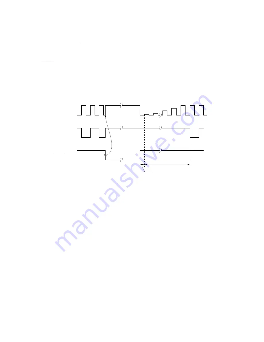
When a low level is input to RESET input pin, system reset is performed. The hardware enters the states listed
in Figure 25-1. Since the oscillation of the main system clock unconditionally stops during the reset period, the current
consumption of the entire system can be reduced.
When RESET input goes from low to high, the reset state is released. After the count time of the timer for oscillation
stabilization (41.9 ms: in 12.5 MHz operation), the content of the reset vector table is set in the program counter (PC).
Execution branches to the address set in the PC, and program execution starts from the branch destination address.
Therefore, the reset can start from any address.
Figure 25-1. Oscillation of Main System Clock in Reset Period
Main system clock
oscillator
f
CLK
RESET input
Oscillation is
unconditionally stopped
during the reset period.
Timer count time for
oscillation stabilization
Time until clock
starts oscillating
To prevent error operation caused by noise, a noise eliminator based on an analog delay is installed at RESET
input pin.


