510
CHAPTER 26 ROM CORRECTION
User’s Manual U12697EJ3V0UM
26.2 ROM Correction Configuration
ROM correction includes the following hardware.
Table 26-2. ROM Correction Configuration
Item
Configuration
Register
ROM correction address register H, L (CORAH, CORAL)
Control register
ROM correction control register (CORC)
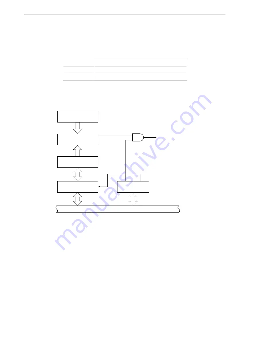
A ROM correction block diagram is shown in Figure 26-1, and Figure 26-2 shows an example of memory mapping.
Figure 26-1. ROM Correction Block Diagram
Internal bus
Instruction fetch address
Comparator
Correction address
pointer n
ROM correction address
register (CORAH, CORAL)
Match
Correction branch
process request signal
(CALLT command)
ROM correction control register
(CORC)
CORENn CORCHm
Remark
n = 0 to 3, m = 0, 1


