CHAPTER 3 PIN FUNCTIONS
User’s Manual U13045EJ2V0UM00
44
3.3 Pin Input/Output Circuits and Recommended Connection of Unused Pins
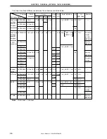
The input/output circuit type for each pin and the recommended connection of pins are shown in Table 3-1.
For the input/output circuit configuration of each type, refer to Figure 3-1.
Table 3-1. Types of Pin Input/Output Circuits and Recommended Connection of Unused Pins
Pin Name
Input/Output Circuit Type
Input/Output
Recommended Connection of Unused Pins
P00 to P03
5-A
Input/output
Input:
Independently connect these pins to V
DD
or
P10, P11
V
SS
via a resistor.
P20/SCK20/ASCK20
8-A
Output: Leave open
P21/SO20/TxD20
P22/SI20/RxD20
P23/INTP0/CPT20/SS20
P24/INTP1/TO80/TO20
P25/INTP2/TI80
P50 to P53
13-W
Input:
Independently connect these pins to V
DD
via a
(Mask ROM version)
resistor.
P50 to P53
13-V
Output: Leave open
(
µ
PD78F9116, 78F9136)
P60/ANI0 to P63/ANI3
9-C
Input
Connect to V
DD
or V
SS
.
AV
DD
—
—
Connect to V
DD
.
AV
SS
Connect to V
SS
.
RESET
2
Input
—
IC0
—
—
Connect directly to V
SS
.
Summary of Contents for mPD789101
Page 2: ...2 User s Manual U13045EJ2V0UM00 MEMO...
Page 10: ...10 User s Manual U13045EJ2V0UM00 MEMO...
Page 16: ...User s Manual U13045EJ2V0UM00 16 MEMO...
Page 46: ...User s Manual U13045EJ2V0UM00 46 MEMO...
Page 72: ...72 User s Manual U13045EJ2V0UM00 MEMO...
Page 86: ...User s Manual U13045EJ2V0UM00 86 MEMO...
Page 94: ...User s Manual U13045EJ2V0UM00 94 MEMO...
Page 102: ...User s Manual U13045EJ2V0UM00 102 MEMO...
Page 128: ...User s Manual U13045EJ2V0UM00 128 MEMO...
Page 148: ...User s Manual U13045EJ2V0UM00 148 MEMO...
Page 162: ...User s Manual U13045EJ2V0UM00 162 MEMO...
Page 218: ...User s Manual U13045EJ2V0UM00 218 MEMO...
Page 238: ...User s Manual U13045EJ2V0UM00 238 MEMO...
Page 240: ...User s Manual U13045EJ2V0UM00 240 MEMO...
Page 256: ...User s Manual U13045EJ2V0UM00 256 MEMO...
Page 258: ...258 User s Manual U13045EJ2V0UM00 MEMO...


