background image

English-5

English

This device cannot be used or installed without the Tabletop
Stand or other mounting accessory for support. For proper
installation it is strongly recommended to use a trained,
NEC authorized service person. Failure to follow NEC
standard mounting procedures could result in damage to the
equipment or injury to the user or installer. Product warranty
does not cover damage caused by improper installation.
Failure to follow these recommendations could result in
voiding the warranty.

Mounting

DO NOT mount the monitor yourself. Please ask dealer.
For proper installation it is strongly recommended to use a
trained, qualified technician. Please inspect the location
where the unit is to be mounted. Mounting on wall or ceiling
is the customer’s responsibility. Not all walls or ceilings are
capable of supporting the weight of the unit. Product
warranty does not cover damage caused by improper
installation, remodelling, or natural disasters. Failure to
comply with these recommendations could result in voiding
the warranty.

DO NOT block ventilated openings with mounting
accessories or other accessories.

For NEC Qualified Personnel:

To insure safe installation, use two or more brackets to
mount the unit. Mount the unit to at least two points on the
installation location.

Please note the following when mounting
on wall or ceiling

When using mounting accessories other than those that
are NEC approved, they must comply with the VESA-
compatible (FDMlv1) mounting method.

NEC strongly recommends
using size M6 screws
(9-10 mm + thickness
of bracket and washer in
length). If using screws
longer than 9-10 mm,
check the depth of the hole.
(Recommended Fasten
Force: 310 - 410 N•cm)
NEC recommends mounting
interfaces that comply
with UL1678 standard in
North America.

Prior to mounting, inspect the installation location to
insure that it is strong enough to support the weight of
the unit so that the unit will be safe from harm.

Refer to the instructions included with the mounting
equipment for detailed information.

Weight of LCD assembly:

-

MultiSync V321: 14.3 kg/31.5 lbs

-

MultiSync V421: 20.5 kg/45.2 lbs

-

MultiSync V461: 24.0 kg/52.9 lbs

Installation

Mounting location

The ceiling and wall must be strong enough to support
the monitor and mounting accessories.

DO NOT install in locations where a door or gate can hit
the unit.

DO NOT install in areas where the unit will be subjected
to strong vibrations and dust.

DO NOT install near where the main power supply
enters the building.

Do not install where people can easily grab and hang
onto the unit or the mounting apparatus.

When mounting in a recessed area, as in a wall, leave at
least 4 inches (10cm) of space between the monitor and
the wall for proper ventilation.

Allow adequate ventilation or provide air conditioning
around the monitor, so that heat can properly dissipate
away from the unit and mounting apparatus.

Mounting on ceiling

Ensure that the ceiling is sturdy enough to support the
weight of the unit and the mounting apparatus over time,
against earthquakes, unexpected vibrations, and other
external forces.

Be sure the unit is mounted to a solid structure within the
ceiling, such as a support beam. Secure the monitor
using bolts, spring lock washers, washer and nut.

DO NOT mount to areas that have no supporting internal
structure. DO NOT use wood screws or anchor screws
for mounting. DO NOT mount the unit to trim or to
hanging fixtures.

Maintenance

Periodically check for loose screws, gaps, distortions, or
other problems that may occur with the mounting
apparatus. If a problem is detected, please refer to
qualified personnel for service.

Regularly check the mounting location for signs of
damage or weakness that may occur over time.

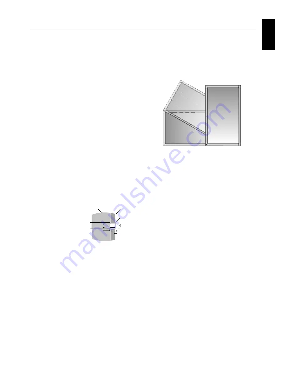
Orientation

When using the display in the portrait position, the
monitor should be rotated clockwise so that the left side
is moved to the top and the LED indicator light is on the
bottom. This will allow for proper ventilation and will
extend the lifetime of the monitor. Improper ventilation
may shorten the lifetime of the monitor.

Mounting
Bracket

Screw

Washer

Unit

9-10 mm

Thickness
of bracket
and washer

Screw length should equal
depth of hole (9-10 mm) + the
thickness of mounting bracket
and washer. Bracket hole
should be under 

φ

 7 mm.

under

φ

 7 mm

Summary of Contents for MultiSync V461

Page 1: ...User s Manual MultiSyncV321 MultiSyncV421 MultiSyncV461...

Page 2: ...and OFF Modes English 16 Power Indicator English 17 Using Power Management English 17 Selecting a video source English 17 Picture Size English 17 Picture Mode English 17 Information OSD English 18 OSD...

Page 3: ...in order to avoid any problems Declaration of the Manufacturer We hereby certify that the color monitor MultiSync V321 L329N8 MultiSync V421 L429N9 MultiSync V461 L469NA are in compliance with Council...

Page 4: ...a Increase the separation between the equipment and receiver Connect the equipment into an outlet on a circuit different from that to which the receiver is connected Consult your dealer or an experien...

Page 5: ...r because of set reliability If using the cooling fan continuously it s recommended to wipe holes a minimum of once a month When using a LAN cable do not connect to a peripheral device with wiring tha...

Page 6: ...mp M4 x 8 x 2 Screw for main switch cover 3 x 6 x 2 CD ROM CD ROM Screw for clamp M4 x 8 x 2 1 Type and number of power cords included will depend on the where the LCD monitor is to be shipped When mo...

Page 7: ...of LCD assembly MultiSync V321 14 3 kg 31 5 lbs MultiSync V421 20 5 kg 45 2 lbs MultiSync V461 24 0 kg 52 9 lbs Installation Mounting location The ceiling and wall must be strong enough to support th...

Page 8: ...is for V321 Use the Thumbscrews included with ST 3215 ST 4020 is for V421 and V461 V421 and V461 are not mentioned in ST 4020 manual Before using optional table top stand remove installed thumbscrews...

Page 9: ...order to prevent the monitor from falling Fasten the cord or chain to the monitor using the provided clamp and screw Before attaching the LCD monitor to the wall make sure that the wall can support th...

Page 10: ...power ON OFF See also page 16 Control Key Lock Mode This control completely locks out access to all Control Key functions To activate the control key lock function press both and and hold down simult...

Page 11: ...extension blocks included in speaker as if being mounted on P461 V421 is not mentioned in SP P4046 manual LAN port RJ 45 LAN connection See page 25 Kensington Lock For security and theft prevention AC...

Page 12: ...on Turns on off mute function VOLUME UP DOWN button Increase decrease audio output level Wireless Remote Control DVI VGA RGB HV HDMI DVD HD VIDEO1 VIDEO2 S VIDEO DVI VGA RGB HV HDMI DVD HD VIDEO1 VIDE...

Page 13: ...in 30 within a distance of about 3 5 m 10 ft Caution Important the remote control system may not function when direct sunlight or strong illumination strikes the remote control sensor of the LCD monit...

Page 14: ...r when it was packaged beneath the LCD monitor so as not to scratch the panel 2 Install the remote control batteries The remote control is powered by two 1 5V AAA batteries To install or replace batte...

Page 15: ...ents such as brightness or contrast when required 10 Recommended Adjustments To reduce the risk of the Image Persistence please adjust the following items based on the application being used POWER SAV...

Page 16: ...Analog Computer Digital Connecting terminal DVI DVI D HDMI DVD HD 5BNC S VIDEO VIDEO1 BNC VIDEO2 5BNC DVI DVI D VGA RGB HV 5BNC Setting in Terminal Mode DVI MODE DVI HD RAW EXPAND 1 BNC MODE COMPONEN...

Page 17: ...024 64 kHz 60 Hz Compressed image 1600 x 1200 75 kHz 60 Hz Compressed image Compressed image 1920 x 1080 66 6 kHz 60 Hz Compressed image Recommended resolution Resolution Remarks Scanning frequency If...

Page 18: ...l turn green while powered on and will turn red while powered off NOTE The Main Power Switch must be in the ON position in order to power up the monitor using the remote control or the Power Button on...

Page 19: ...card used this function may not operate Selecting a video source To view a video source Use the input button to set HDMI VIDEO1 VIDEO2 or S VIDEO Use the COLOR SYSTEM menu to set AUTO PAL NTSC PAL60 4...

Page 20: ...r setting to be adjusted Press EXIT button to exit Control Panel Press button to select Main menu and press Up Down button to enter Sub menu Press button to make setting to be adjusted OR EXIT button...

Page 21: ...s mode is better suited for movies which is converted 24 Frames sec source to DVD Video PICTURE RESET Resets the all settings within the PICTURE menu back to factory setting AUTO SETUP Press SET butto...

Page 22: ...n to operate SCHEDULE RESET Resets the all settings within the SCHEDULE menu back to factory setting except DATE AND TIME setting PIP MODE Selects Picture in Picture mode See page 10 OFF Normal mode P...

Page 23: ...hen TILE MATRIX is activated POWER ON DELAY Adjusts the delay time between being in standby mode and entering power on mode POWER ON DELAY time is selectable from OFF 2 4 6 8 10 20 30 40 and 50 sec EX...

Page 24: ...d bright areas SCAN CONVERSION Selects IP Interlace to Progressive converter function INPUT HDMI DVD HD S VIDEO VIDEO1 VIDEO2 only PROGRESSIVE Enables the IP function to convert interlace signal to pr...

Page 25: ...ology may experience a phenomenon known as Image Persistence Image Persistence occurs when a residual or ghost image of a previous image remains visible on the screen Unlike CRT monitors LCD monitors...

Page 26: ...not connect to other types of equipment To control monitor or multiple monitors that are daisy chained together please use the control command Instructions for the control command can be found on the...

Page 27: ...rsion for the web browser This device uses JavaScript and Cookies and the browser should be set to accept these functions The setting method will vary depending on the version of browser Please refer...

Page 28: ...pd nec co jp index html for the address or the entry column of the URL Example 2 When the IP address of the monitor is 192 168 73 1 access is gained to the mail alert settings by specifying http 192...

Page 29: ...sed Click this button to reflect the above settings Click this button to send a test mail to check if your settings are correct A reply to a test mail will be displayed HOST NAME DOMAIN NAME ALERT MAI...

Page 30: ...r power consumption level when on but not in use saving two thirds of your monitor energy costs reducing emissions and lowering the air conditioning costs of the workplace FullScan Capability Allows y...

Page 31: ...signal timings If your text is garbled change the video mode to non interlace and use 60Hz refresh rate Image of component signal is greenish Check to see if the DVD HD input connector is selected LED...

Page 32: ...C 0 286 Vp p 75 ohm NTSC 0 3 Vp p 75 ohm PAL SECAM NTSC PAL SECAM 4 43NTSC PAL60 VIDEO1 BNC Composite 1 0 Vp p 75 ohm VIDEO2 2 BNC NTSC PAL SECAM 4 43NTSC PAL60 Output Signal RGB 15pin Mini D sub Anal...

Page 33: ...286 Vp p 75 ohm NTSC 0 3 Vp p 75 ohm PAL SECAM NTSC PAL SECAM 4 43NTSC PAL60 VIDEO1 BNC Composite 1 0 Vp p 75 ohm VIDEO2 2 BNC NTSC PAL SECAM 4 43NTSC PAL60 Output Signal RGB 15pin Mini D sub Analog...

Page 34: ...Vp p 75 ohm NTSC 0 3 Vp p 75 ohm PAL SECAM NTSC PAL SECAM 4 43NTSC PAL60 VIDEO1 BNC Composite 1 0 Vp p 75 ohm VIDEO2 2 BNC NTSC PAL SECAM 4 43NTSC PAL60 Output Signal RGB 15pin Mini D sub Analog RGB...

Page 35: ...gnment RS 232C input Pin No Name 1 connected to 7 8 2 RXD 3 TXD 4 connected to 6 5 GND 6 connected to 4 7 connected to 1 8 8 connected to 1 7 9 NC 1 6 5 9 D SUB 9P This LCD monitor uses RXD TXD and GN...

Page 36: ...nitor features an advanced energy saving capability When a VESA Display Power Management Signalling DPMS Standard signal is sent to the monitor the Energy Saving mode is activated The monitor enters a...

Reviews: