Setting Up Your Server 3-17
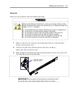
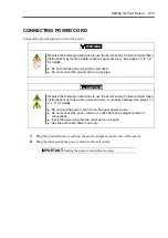
TURNING ON THE SERVER
Power on your system as follows.
1.
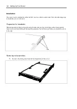
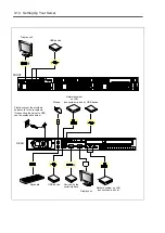
Make sure all external devices, such as a video display, keyboard, and mouse (optional)
have been connected, and the power cords are connected.
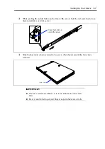
2.
Power on the video display and any other external devices.
NOTE:
If the server power cord(s) is connected to a power control
unit such as an UPS (Uninterruptible Power Supply), make sure that the
power control unit is powered on.
3.
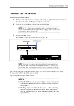
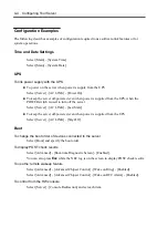
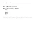
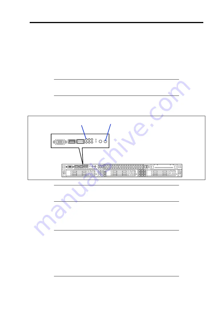
Press the POWER switch.
The POWER LED on the front of the server comes on.
NOTE:
Connect the power cord and wait about five seconds before
pressing the POWER switch. The POWER switch does not work in a
few seconds after connecting the power cord due to firmware start-up.
The Power On Self-Test (POST) runs while "NEC" logo is displayed to diagnose the system
hardware. See "POST" described later for details.
Upon completion of POST, the OS starts.
NOTES:
When the POST detects any error, it displays an error message and
its measure on the display unit. See Chapter 8 for details of POST
error message.
The DC power is turned off at the first power-on after connecting
the power cord or at rebooting of the server by the Reset switch.
After several seconds, the DC power is turned on again. This is not
a power failure.
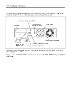
POWER switch
POWER LED
Summary of Contents for N8100-14522F
Page 16: ...x This page is intentionally left blank...
Page 122: ...4 54 Configuring Your Server This page is intentionally left blank...
Page 178: ...6 22 Installing and Using Utilities This page is intentionally left blank...
Page 190: ...7 12 Maintenance This page is intentionally left blank...
Page 254: ...A 2 Specifications This page is intentionally left blank...
Page 262: ...C 2 IRQ This page is intentionally left blank...
Page 316: ...F 2 Using a Client Computer Which Has a CD Drive This page is intentionally left blank...
Page 320: ...G 4 Product Configuration Record Table This page is intentionally left blank...


