background image

2. Interrupt Lines 


Express5800/GT110e-S  User’s Guide 

139 

Chapter 4  Appendix 

2.


Interrupt Lines 

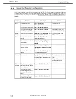
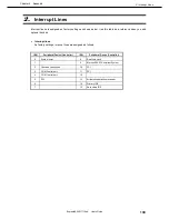
Interrupt lines are assigned as factory settings as shown below. Use this table as a reference when you add 
optional devices.   


Interrupt lines 


As factory settings, interrupt lines are assigned as follows. 


IRQ 

Peripheral Device (Controller) 

IRQ 

Peripheral Device (Controller) 

System timer 

Real-time clock 


Microsoft ACPI-Compliant System 

Cascade connection 

10 

PCI 

COM 2 serial port 

11 

PCI 

COM 1 serial port 

12 


PCI 

13 

Arithmetic operation processor 


14 

Primary IDE 


15 

Secondary IDE 


Summary of Contents for N8100-1891F

Page 1: ...ries 10 020 04 101 01 July 2012 First Edition NEC Corporation 2012 Express5800 GT110e S EXP281A User s Guide Model Number N8100 1891F 1892F 1894F Chapter 1 General Description Chapter 2 Preparations C...

Page 2: ...ons connection of peripheral devices and ideal location for this server Chapter 3 Setting Up Your Server System BIOS configurations and summary of EXPRESSBUILDER Chapter 4 Appendix Specifications and...

Page 3: ...atest editions 12 Precautions for Use Be Sure to Read 13 Safety precautions 13 Symbols used in this document and on warning labels 14 Safety notes 15 General 15 Power supply and power cord use 16 Inst...

Page 4: ...1 1 Safety Precautions 45 1 2 Anti static Measures 46 1 3 Overview of Installation and Removal 47 1 4 Removing the Side Cover 48 1 5 Removing the Front Bezel 49 1 6 Internal Flash Memory 50 1 6 1 Inst...

Page 5: ...stalling an expansion 2 5 inch HDD cage 94 1 12 2 Installation 96 1 12 3 Removal 97 1 12 4 Removing the 2 5 inch HDD cage for additional drives 97 1 13 Optical Disk Drive 98 1 13 1 Replacing drives 98...

Page 6: ...On Screen Items and Key Usage 126 2 4 Cases that Require Configuration 128 3 EXPRESSSCOPE ENGINE 3 130 3 1 Overview 130 3 2 EXPRESSSCOPE ENGINE 3 Network configuration 131 4 EXPRESSBUILDER 133 4 1 Fe...

Page 7: ...ccur Note Indicates items that must be confirmed when handling the server or operating software Tips Indicates information that is helpful to keep in mind when using this server Optical disk drives Th...

Page 8: ...003 R2 2 Windows Server 2003 R2 Standard Windows Server 2003 R2 Enterprise Windows Server 2003 2 Windows Server 2003 Standard Windows Server 2003 Enterprise Windows 7 Windows 7 Professional 64 bit x64...

Page 9: ...or trademarks of Adaptec Inc of the United States LSI and the LSI logo design are trademarks or registered trademarks of LSI Corporation Adobe the Adobe logo and Acrobat are trademarks of Adobe System...

Page 10: ...n d Industrie Canada Cet appareil num rique de la classe A est conforme la norme NMB 003 du Canada CE Australia and New Zealand Statement This is a Class A product In domestic environment this product...

Page 11: ...ket EEE Y netmeli ine Uygundur CCC Pb Hg Cd Cr PBB PBDE HDD DVD SJ T11363 2006 SJ T11363 2006 Vietnam RoHS information relevant for Vietnam market Complying with CIRCULAR No 30 2011 TT BCT Hanoi Augus...

Page 12: ...or omissions please contact your retailer 5 Regardless of these 4 items NEC Corporation assumes no responsibility for effects resulting from operations 6 The sample values used in this document are no...

Page 13: ...ls WARNING or CAUTION is used to indicate a degree of danger These terms are defined as follows WARNING Indicates there is a risk of death or serious personal injury CAUTION Indicates there is a risk...

Page 14: ...shock or fire may be caused Do not touch the server with wet hand Otherwise an electric shock may be caused Do not touch the component specified by this symbol Otherwise an electric shock or burn may...

Page 15: ...esent If smoke odor or noise is present immediately turn off the server and disconnect the power plug from the outlet then contact the store where you purchased the product or your maintenance service...

Page 16: ...If you want to use an AC cord set with a ground wire of class OI be sure to connect the ground wire before inserting the power plug into the outlet Before disconnecting the ground wire be sure to disc...

Page 17: ...with staples or equivalents Do not pinch the power cord Keep chemicals away from the power cord Do not place any object on the power cord Do not alter modify or repair the power cord Do not use a dam...

Page 18: ...s dust chemicals that accelerate corrosion such as NaCl or sulfur or conductive materials Failure to follow this warning may cause the wiring on the printed wiring board to short circuit leading to fi...

Page 19: ...move lithium NiMH or Li ion batteries The server contains the lithium NiMH or Li ion battery some optional devices have a lithium NiMH or Li ion battery installed Do not remove the battery Placing a b...

Page 20: ...fall resulting in personal injury or property damage Do not place any object that weighs 5 kg or more on top of horizontally mounted servers The maximum weight that can be placed on top of the server...

Page 21: ...ial hazards This label is either attached or printed on the component to draw attention from users to potential hazards involved in handling the server Do not remove or black out this label and keep i...

Page 22: ...the server after power off Turn off the server and unplug the power cord before moving it Regularly clean the server to prevent various types of failure Refer to Chapter 1 Maintenance 2 Daily Mainten...

Page 23: ...wait for a sufficient period to use the server and components in the operating environment Reference Time effective at avoiding condensation in winter 10 C or more differences between the room tempera...

Page 24: ...from reflecting bright lights and to make the display contents easy to see Working without adjusting the display to a comfortable angle makes it difficult for you to maintain a proper posture and you...

Page 25: ...res of this server and the name of each part 1 Introduction 2 Accessories Verify the condition of your server s accessories 3 Standard Features Check and maintain the server system by using the functi...

Page 26: ...odel Intel Xeon processor Intel Pentium processor NEC s latest technology and architectures realize high power and high speed operation that cannot be matched by existing servers The server is designe...

Page 27: ...505 2 1 EXPRESSBUILDER 4 Getting Started Power cord x 1 SDR Update CD ROM 1 Only for 3 5 inch disk models The number of the cable depends on the Hard Disk Drive configuration 2 Only for 2 5 inch disk...

Page 28: ...ion BIOS password feature Management utilities NEC ESMPRO ExpressUpdate Remote controlling featuer EXPRESSSCOPE Engine 3 RAID System management utility Universal RAID Utility Hard disk drive monitorin...

Page 29: ...Diagnosis T D utility Easy setup EXPRESSBUILDER setup utility SETUP BIOS SETUP utility Maintenance features Off line tool Memory dump feature using the DUMP switch Feature to back up and restore BIOS...

Page 30: ...nd video System environment Temperature Monitors the temperature inside of the chassis Fan Monitors the fans Voltage Monitors the voltage inside of the chassis Power supply Monitors the power supply u...

Page 31: ...Management By using NEC ESMPRO Manager and ExpressUpdate Agent you can manage firmware or software on the server and update them by applying an update package This function automatically updates mult...

Page 32: ...being accessed The LED lights amber if a hard disk drive error occurs 5 STATUS LED green amber This LED indicates the server status It lights green when the server is operating normally 6 USB connecto...

Page 33: ...is LED indicates the server status It lights green when the server is operating normally and lights or flashes amber when errors occur 6 USB connectors front These connectors are used to connect devic...

Page 34: ...nly when there is something wrong with EXPRESSSCOPE Engine 3 BMC 8 USB connectors These connectors are used to connect devices that support the USB interface 9 LAN connectors Supports 1000BASE T 100BA...

Page 35: ...al Description 4 3 Internal view 3 5 inch drive model air cooled type 1 Power supply unit 2 Cooling fan CPU 3 DIMM slots 4 3 5 inch hard disk drive 5 Optical disk drive 6 3 5 inch Expansion Bay 5 Moth...

Page 36: ...l liquid cooling type 1 Power supply unit 2 Liquid cooling unit for cooling CPU 3 DIMM slots 4 3 5 inch hard disk drive 5 Optical disk drive 6 3 5 inch Expansion Bay 7 Motherboard 8 Cooling fan front...

Page 37: ...tion 2 5 inch drive model air cooled type 1 Power supply unit 2 Cooling fan CPU 3 DIMM slot 4 SAS backplane 5 2 5 inch hard disk drive 6 Cooling fan HDD 7 Optical disk drive 8 3 5 inch Expansion Bay 9...

Page 38: ...pe 1 Power supply unit 2 Liquid cooling unit for cooling CPU 3 DIMM slot 4 SAS backplane 5 2 5 inch hard disk drive 6 Cooling fan HDD 7 Optical disk drive 8 3 5 inch Expansion Bay 9 Motherboard 10 Coo...

Page 39: ...al port COM B connector 17 SPI Flash Mezzanine connector EXPRESSSCOPE profile key SPI flash memory has been installed where BIOS and BMC configuration data is stored Move it when replacing MB to keep...

Page 40: ...his section explains the indication and meanings of the server LEDs 3 5 inch drive model 2 5 inch drive model Front view Rear view Disk LED POWER LED Disk Access LED Optical disk LED STATUS LED LINK A...

Page 41: ...ETUP and replace it as soon as possible An uncorrectable memory error has often occurred Off The power is off Turn on the server POST is in progress The STATUS LED will turn green after POST completes...

Page 42: ...g accessed When RAID System using an optional RAID Controller is configured or RAID System is configured with 2 5 inch disk drive model this LED lights amber if hard disk drive error occurs It lights...

Page 43: ...etwork interface is used The two LAN ports for data transmission support 1000BASE T 100BASE TX and 10BASE T and the LED indicates which network interface is being used Amber Operating with 1000BASE T...

Page 44: ...his chapter describes preparations for using this server 1 Installing Internal Optional Devices You can skip this section if you did not purchase any optional devices 2 Installation and Connection You...

Page 45: ...warranty period 1 1 Safety Precautions Be sure to observe the following precautions to install and remove optional devices properly and safely WARNING Be sure to observe the following precautions to...

Page 46: ...periodically touching a metal surface while working on the components Select a suitable work space Work with the server on the anti static or concrete floor When you work with the server on a carpet...

Page 47: ...pter 2 1 4 Removing the Side Cover 5 Remove the front bezel if applicable Refer to Chapter 2 1 5 Removing the Front Bezel 6 Depending on the components to be installed or removed follow the procedure...

Page 48: ...cedure 1 Refer to steps 1 to 3 in Chapter 2 1 3 Overview of Installation and Removal for preparations 2 Unlock the padlock attached to the chassis if applicable 3 Lay the server so that the side cover...

Page 49: ...r preparations 2 Release the three tabs on the front bezel in the direction of the arrow shown in the image and then pull the front bezel forward slightly until it comes off the frame Important If you...

Page 50: ...lash Memory 1 6 1 Installation Install the Internal Flash Memory in the following procedure 1 Refer to steps 1 to 5 in Chapter 2 1 3 Overview of Installation and Removal for preparations 2 Attach the...

Page 51: ...stalling a DIMM from a third party may cause the server to fail You will be charged to repair failures or damages caused by the use of such products even within the warranty period Read through Chapte...

Page 52: ...rprise Edition Windows Server 2008 Enterprise x86 Edition 64 GB Windows Server 2003 R2 Enterprise x64 Edition 1 TB Windows Server 2008 Enterprise x64 Windows Server 2008 R2 Enterprise x64 2 TB 1 7 2 I...

Page 53: ...nd keyslot preventing being wrongly inserted 5 Firmly close the lever 6 Continue to install or remove internal optional devices mount and connect the server and turn it on 7 Confirm that no error mess...

Page 54: ...ng too much pressure on a DIMM or pulling a DIMM at an angle may break the DIMM or slot Gently pull it straight out of the slot 4 Assemble the server 5 Turn on the server and confirm that no error mes...

Page 55: ...tialize the Hard Disk Drives If the Hard Disk Drive used in the RAID System contains valuable data be sure to backup the Hard Disk Drive before installing the RAID Controller and configuring the RAID...

Page 56: ...as shown below Jumper pins on motherboard SWRAID Change jumper setting to 2 3 Enabled Backplane for 2 5 inch Hard Disk Drive provided with 2 5 inch models J7 Onboard SATA controller Set to 1 2 1 2 3 1...

Page 57: ...cable is required instead of using the interface cable supplied with the server For 3 5 inch Hard Disk Drives K410 253 00 internal SAS SATA cable For 2 5 inch Hard Disk Drives K410 180 00 internal SAS...

Page 58: ...3 RAID 10 4 4 RAID 50 6 Use SAS SATA Hard Disk Drives or SSDs that have the same capacity and rotational speed As the size of Logical Drive cannot be specified in RAID 10 with the on board RAID Contr...

Page 59: ...in OS system event log Models with 3 5 inch Hard Disk Drives installed Insert position numbers displayed on the server Slot numbers indicated On board RAID Controllers Optional RAID Controllers N8103...

Page 60: ...ions The insert position number displayed on the server 1 0 0 1 2 Models with 2 5 inch Hard Disk Drives installed when expansion 2 5 inch HDD cages are installed 0 1 2 HDD cage 4 5 Models with 3 5 inc...

Page 61: ...me part of the server to discharge the static electricity from your body Do not drop or bump the backup battery For recycling and disposing the backup battery refer to the user s guide that comes with...

Page 62: ...1 5 Removing the Front Bezel remove the side cover and front bezel Installing the connection board Install the connection board to the RAID Controller 1 Orient the remote battery connection board so t...

Page 63: ...ow connect the battery control cable into the battery pack Check the orientation of the connector and connect the cable straight into the connector Make sure the connector is oriented correctly by che...

Page 64: ...inch Hard Disk Drive models 1 Remove the file device or dummy cover For the dummy cover pull it toward you while pressing the tab on the right 2 Remove the two screws from the blank cover 3 Pass the b...

Page 65: ...Chapter 2 Preparations 4 Engage the tabs of the bracket with the grille of the blank cover and fix it with the attached screw large Refer to the image below for the installation position Tab Tab Insta...

Page 66: ...arations 5 Engage the tabs at the lower part of the blank cover with the chassis and fix it with the two screws If the cable is too long arrange it neatly such as by coiling it once within the chassis...

Page 67: ...to release the blank cover 2 Pass the bracket containing the battery and which is connected to the remote cable through the opening from which the blank cover was removed 3 Engage the tabs of the bra...

Page 68: ...e 68 Chapter 2 Preparations 4 While pushing the blank cover to the right fix it with one screw If the cable is too long arrange it neatly such as by coiling once within the chassis This concludes the...

Page 69: ...actual life depends on the operating environment and conditions If it has been used for 2 years or more the maximum data backup time is not guaranteed Replace it soon with a new battery pack referrin...

Page 70: ...Overview of Installation and Removal for preparations 2 While referring to Chapter 2 1 4 Removing the Side Cover and 1 5 Removing the Front Bezel remove the side cover and front bezel 3 If a RAID Con...

Page 71: ...y pack to 2 5 inch Hard Disk Drive models 1 Remove the file device or dummy cover For the dummy cover pull it toward you while pressing the tab on the right 2 Remove the two screws from the blank cove...

Page 72: ...Chapter 2 Preparations 4 Engage the tabs of the bracket with the grille of the blank cover and fix it with the attached screw large Refer to the image below for the installation position Tab Engage th...

Page 73: ...s5800 GT110e S User s Guide 73 Chapter 2 Preparations 5 Engage the tabs at the lower part of the blank cover with the chassis and fix it with the two screws If the cable is too long arrange it neatly...

Page 74: ...g a battery pack to 3 5 inch Hard Disk Drive models 1 Remove one screw from the blank cover and slide it to the side to release the blank cover 2 Engage the tabs of the bracket with the grille of the...

Page 75: ...onal Devices Express5800 GT110e S User s Guide 75 Chapter 2 Preparations 3 While pushing the blank cover to the right fix it with one screw If the cable is too long arrange it neatly such as by coilin...

Page 76: ...the battery control cable to the connector board on the RAID Controller Check the orientation of the connector and connect the cable straight into the connector Be careful not to press it in at an ang...

Page 77: ...tions 2 Install a RAID Controller into the PCI slot and fix it in place Be careful not to disconnect any cables 3 Connect the cables and components that you removed earlier 1 9 4 Removal For removing...

Page 78: ...CI cards refer to Chapter 2 1 10 2 List of option devices and installation slots to prevent mistaking slot numbers Configure the Option ROM in PCI Configuration according to the application of the ins...

Page 79: ...able below PCI device Bus number Device number Function number Onboard NIC1 4h 0 0 Onboard NIC2 4h 0 1 Slot 1 2h 0 Slot 2 3h 0 Slot 3 1h 0 Slot 4 6h 0 0 Set Disabled for the optional ROM of a LAN devi...

Page 80: ...ports per team N8104 132 1000BASE T connection board 2ch Card performance PCI EXPRESS x1 N8104 133 1000BASE T connection board 4ch Card performance PCI EXPRESS x2 N8117 01A Additional RS 232C connect...

Page 81: ...teams per system Up to 2 ports per team N8104 132 1000BASE T connection board 2ch Card performance PCI EXPRESS x1 N8104 133 1000BASE T connection board 4ch Card performance PCI EXPRESS x2 N8117 01A A...

Page 82: ...to 2 teams per system Up to 2 ports per team N8104 132 1000BASE T connection board 2ch Card performance PCI EXPRESS x1 N8104 133 1000BASE T connection board 4ch Card performance PCI EXPRESS x2 Can be...

Page 83: ...r settings on the card are properly set according to the instruction manual supplied with the card if necessary 2 Refer to Chapter 2 1 3 Overview of Installation and Removal for preparations 3 Remove...

Page 84: ...securely connect to the slot Important If you have trouble installing the card remove the card once and try again If you apply excessive pressure on the card there is a risk of breaking the card 7 Cl...

Page 85: ...in the card contains a BIOS utility the startup message banner is displayed in ascending order of the PCI bus numbers 1 10 5 Removal Remove a PCI card connected to a PCI slot by using the following p...

Page 86: ...uid cooling model The component parts for N8117 01A are as follows Item no Item name Specification Amount Remarks 1 RS 232C connector Kit User s Guide 856 125671 002 1 2 RS 232C cable A 804 063264 020...

Page 87: ...Chapter 2 Preparations 5 Remove the expansion blank cover aligned with the slot where you are going to install a card Important Keep the removed blank cover for future use 6 Make sure that you are pro...

Page 88: ...ollowing for the position of the COM connector for internal connections Important If connecting the cable fit it to the polarizing key of the connector and be careful not to connect it improperly The...

Page 89: ...e installed in the 3 5 inch Hard Disk Drive model Important Use Hard Disk Drives specified by NEC Installing a third party Hard Disk Drive might cause a failure of the server and the Hard Disk Drive Y...

Page 90: ...Location of the bay where the drives will be installed Serial ATA connector of the connecting motherboard 1st Bottom Serial ATA connector 0 2nd Top Serial ATA connector 1 2 Refer to Chapter 2 1 3 Over...

Page 91: ...vided by this device screw set 505 of four screws to secure the Hard Disk Drive Using screws of a length greater than that required can cause damage to the Hard Disk Drive 10 Install the Hard Disk Dri...

Page 92: ...ent and Disposal in Maintenance Guide 1 Refer to Chapter 2 1 3 Overview of Installation and Removal for preparations 2 Remove the side cover and front bezel while referring to Chapter 2 1 4 Removing t...

Page 93: ...Disk Drives in order from slot 0 and mount the SSDs to the remaining slots You can use a combination of an SAS Hard Disk Drive in the standard cage and an SATA Hard Disk Drive in the expansion cage I...

Page 94: ...ives by using the following procedure 1 Refer to Chapter 2 1 3 Overview of Installation and Removal for preparations 2 Remove the side cover and front bezel while referring to Chapter 2 1 4 Removing t...

Page 95: ...Connect the fan cable of the HDD cage to the motherboard For details refer to Chapter 2 1 15 Connecting cables 9 Push the HDD cage all the way into the server until it locks with a clicking sound 10 U...

Page 96: ...s locked when you hear a clicking sound Important Use Hard Disk Drives recommended by NEC For details consult with the store where you made your purchase or your maintenance service company Note Refer...

Page 97: ...4 Close the door and lock with the door lock key 1 12 4 Removing the 2 5 inch HDD cage for additional drives You can remove the 2 5 inch HDD cage for additional drives by using the following procedure...

Page 98: ...to Chapter 2 1 4 Removing the Side Cover and 1 5 Removing the Front Bezel 3 While pressing the latch of the SATA cable disconnect the SATA cable from the optical disk drive 4 While pressing the stopp...

Page 99: ...ots for the installation of backup devices such as optical disk drives and magnetic tape drives As a standard there is one expansion slot Tips Controller board options and internal cables might be req...

Page 100: ...view of Installation and Removal for preparations 2 Remove the side cover and front bezel while referring to Chapter 2 1 4 Removing the Side Cover and 1 5 Removing the Front Bezel 3 While pressing the...

Page 101: ...cable to the installed 3 5 inch device For more information refer to Chapter 2 1 15 Connecting cables 8 Push the device all the way until it locks with a clicking sound 9 Assemble the server 10 Insta...

Page 102: ...isk Drive models When adding Hard Disk Drives connect the cables as in the following figure Install the Hard Disk Drives in order from the bottom Connect the first Hard Disk Drive to SATA0 the second...

Page 103: ...K410 253 00 for use with RAID Controllers Install the Hard Disk Drives in order from the bottom RAID Controller N8103 128 149 151 Motherboard Power supply unit Second Hard Disk Drive First Hard Disk D...

Page 104: ...o display this status connect the LED cable provided with the optional K cord cable K410 253 00 Connect the LED connector on the motherboard to the connector on the RAID Controller Refer to the figure...

Page 105: ...149 150 151 the dedicated cable K410 180 00 is required Install Hard Disk Drives from Slot 0 in ascending order Power supply unit Motherboard Extra battery N8103 141 155 Optical disk drive Slot 0 Firs...

Page 106: ...SATA connector of the cable with the SATA connector number on the motherboard Also connect the cable to the SGPIO connector on the motherboard Install Hard Disk Drives from Slot 0 in ascending order P...

Page 107: ...cannot connect them to the on board SATA controller MB SASBP signal cable Slot 1 Second Hard Disk Drive Optical disk drive Power supply unit Motherboard Internal SATA cable K410 241 00 SATA cable for...

Page 108: ...al USB device Use the dedicated internal USB cable K410 255 00 b If mounting the internal USB device and using Internal Flash Memory Use internal USB cable K410 245 00 to connect the device Motherboar...

Page 109: ...ting the power cables Power cables other than those shown here are not used by the devices 1 For 3 5 inch Hard Disk Drive models 2 For 2 5 inch Hard Disk Drive models P3 P4 P1 P10 P11 P2 P5 Optional d...

Page 110: ...ions 1 16 Attaching the Front Bezel You can attach the front bezel by reversing the removal procedure Insert the three tabs on the lower part of the front bezel into the holes on the front of the serv...

Page 111: ...ted in the holes on the server frame Also make sure that the hooks at the front of the cover are engaged with the server frame when sliding the side cover forward to attach If they are not engaged wit...

Page 112: ...Install and store only in the specified environment The environment suitable for the server is as follows Hold the server firmly and slowly and gently place it in the position in which it is to be in...

Page 113: ...on is connected Place where intense vibration may be generated Place where some objects may be fallen Place near a device generating intense magnetic field such as TVs radios broadcast communication a...

Page 114: ...tion as instructed below Also be sure to attach the vent holes cover for cooling on the top of the server a Removing installing the stabilizer Removing the stabilizer Release the lock plate and slide...

Page 115: ...attach the provided rubber feet to the positions shown in the image Also attach the vent holes cover on the right side of the server the server top if vertically mounted Important If the server is ho...

Page 116: ...lowing precautions to use the server safety Failure to observe the precautions may cause death or serious injury For details refer to Safety precautions in Precautions for Use Do not hold the power pl...

Page 117: ...erver beforehand Some devices from a third party cannot be used with the server You cannot connect directly to the dedicated line through the serial port that is equipped with the server as standard T...

Page 118: ...s Guide 118 Chapter 2 Preparations Display unit Front view Rear view USB devices such as a FD drive A device with serial interface such as a modem USB devices such as a terminal adapter Finally connec...

Page 119: ...outlet provided at the rear of the UPS For details refer to the instruction manual supplied with the UPS In order to link the power supply from the UPS with the power on off of this server the BIOS s...

Page 120: ...ngs by following the instructions in this section 3 EXPRESSSCOPE Engine 3 EXPRESSSCOPE Engine 3 provides useful features through the Baseboard Management Controller BMC 4 EXPRESSBUILDER EXPRESSBUILDER...

Page 121: ...r the power has been turned off 1 Disconnect Flash FDD if applicable 2 Turn on the peripheral devices that connect to the display monitor and the server Note If the power cord is connected to power co...

Page 122: ...he manual that comes with the optional board before any key entry Powering on the server after you installed or removed an optional PCI board or moved it to another slot may display the message that i...

Page 123: ...ontroller which has its dedicated BIOS such as a SAS controller board is installed a message that prompts you to start the dedicated utility to set each board is displayed Example If an optional SAS C...

Page 124: ...an error it displays an error message on the screen or beeps for some errors For descriptions of error messages causes and countermeasures refer to Maintenance Guide Important Take notes on the messag...

Page 125: ...boot In most of cases the SETUP was configured for optimal performance before the server was shipped to you Therefore in most of cases you should not need to use the SETUP utility Use only when the ca...

Page 126: ...the selected item You cannot use this key when a menu which has on the left is selected Enter key Press this key to confirm the selected parameter Esc key Pressing this key takes you to the previous...

Page 127: ...F3 key If you press this key the following window appears If you select Yes restore the parameters of the currently selected item to the default setting This might be different from the parameters con...

Page 128: ...Slot n Option ROM Enabled n is PCI slot number of the RAID Controller Boot Change the boot order of devices Boot Boot Option Priorities Change the boot priority Use remote power on function from mode...

Page 129: ...password 3 times operation stops You cannot operate further Turn off the power Saving changes If you finish configuration select Save Exit and then Save Changes and Exit to save changes and exit If y...

Page 130: ...ge USB memory To enable this feature the optional license for remote management N8115 04 is required Note If N8115 04 Remove KVM and Media License if installed More than one removable drives other tha...

Page 131: ...ppears on the lower left of the screen Press F2 SETUP F3 Internal Flash Memory F4 ROM Utility F12 Network 2 If you press the F4 key at this time ROM utility starts upon completion of POST You can also...

Page 132: ...ress Subnet Mask Tips If Shared BMC LAN is enabled Web feature remote media KVM feature or command line interface feature may be interrupted In this case wait for a while and connect with network agai...

Page 133: ...eature select Tool menu in the menu after boot Storage of documents Stores various documents including User s Guide Installation Guide and Maintenance Guide Documents and some software components are...

Page 134: ...ftware Components Express5800 GT110e S User s Guide 134 Chapter 3 Setup 5 Installing Software Components Continue to install software components such as OS Refer to the instructions below Installation...

Page 135: ...ocedure If the power cord of the server is connected to a UPS refer to the documentation supplied with the UPS or the documentation for the application controlling the UPS 1 Shut down the OS 2 If the...

Page 136: ...Express5800 GT110e S User s Guide 136 NEC Express5800 Series Express5800 GT110e S Appendix 1 Specifications 2 Interrupt Lines 4 4...

Page 137: ...ion slot PCI PCI EXPRESS 3 0 1 slot x8 x8 socket 4 PCI EXPRESS 2 0 2 slot x4 x8 socket 32 bit 33 MHzx1 slot External interface USB Front 2 ports rear 4 ports internal 2 ports version 2 0 compatible Se...

Page 138: ...slot x8 x16 PCI EXPRESS 2 slot x4 x8 socket External interface USB Front 2 ports rear 4 ports internal 2 ports version 2 0 compatible Serial 1 port D sub 9 pin 1 Network 2 ports 100Base T 100Base TS 1...

Page 139: ...you add optional devices Interrupt lines As factory settings interrupt lines are assigned as follows IRQ Peripheral Device Controller IRQ Peripheral Device Controller 0 System timer 8 Real time clock...

Reviews: