


CHAPTER 2 INSTALLATION
MDF Cross Connections
NEAX2000 IVS
2
Installation Procedure Manual
ND-70928 (E), Issue 1.0
Page 127
42
YL-OR
GN
3
T0
T0
T0
RA0
K1
T
RA
17
OR-YL
RD
R0
R0
R0
TA0
K0
R
RB
43
YL-GN
BK
T1
T1
T1
RB0
K3
T
TA
18
GN-YL
YL
R1
R1
R1
TB0
K2
R
TB
44
YL-BR
GN
T2
T2
RA1
K5
T
19
BR-YL
RD
R2
R2
TA1
K4
R
45
YL-SL
BK
T3
T3
RB1
K7
T
20
SL-YL
YL
R3
R3
TB1
K6
R
46
VI-BL
GN
T4
21
BL-VI
RD
R4
47
VI-OR
BK
T5
22
OR-VI
YL
R5
48
VI-GN
GN
T6
23
GN-VI
RD
R6
49
VI-BR
BK
T7
24
BR-VI
YL
R7
50
VI-SL
MN
*
25
SL-VI
MJ
*
*
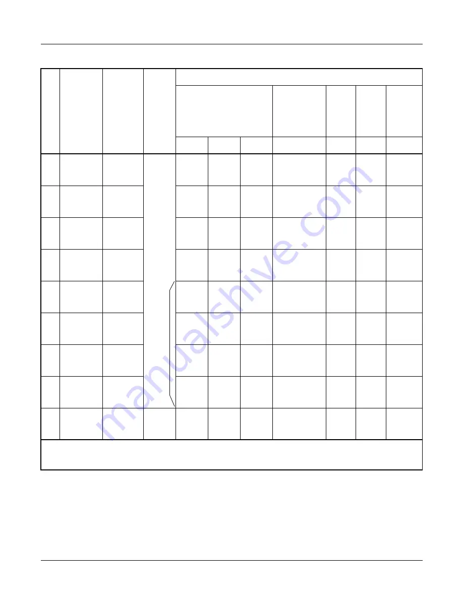
PIN No.50, 25 in PIM0 are connected to external indication equipment for major card minor
alarm.
NOTE 1: PIN No. 46, 21 to 49, 24 on LTC3 cannot be used.
NOTE 2: PIN No. 46, 21 to 49, 24 on LTC2 and LTC3 cannot be used.
NOTE 3: For the Digital Trunk Interface card, use the different LTC connector from the analog
line/trunk card. The digital line should be separated from the analog line.
Table 2-5 LTC0 - LTC3 MDF Cross Connection Information (Continued)
PIN
RUNNING
CABLE
STATION
CABLE
SLOTS
TYPE OF INTERFACE
2 wire D
term
/
SMARTCON/
DSSCON/
DESKCON
4 wire
SMARTCON
(SN610
ATTCON)
EXT.
KEY/
EXT.
RELAY
EXT.
PAGE/
MOH/
BGM
Digital
TRK
NOTE 3
8DLC
4DLC
2DLC
2DLCC
DK00 4COT
DTI
NOTE
2


