


CHAPTER 3 LAMP INDICATIONS AND SWITCH SETTINGS
PN-AP00-B (AP00)
NEAX2000 IVS
2
Installation Procedure Manual
ND-70928 (E), Issue 1.0
Page 233
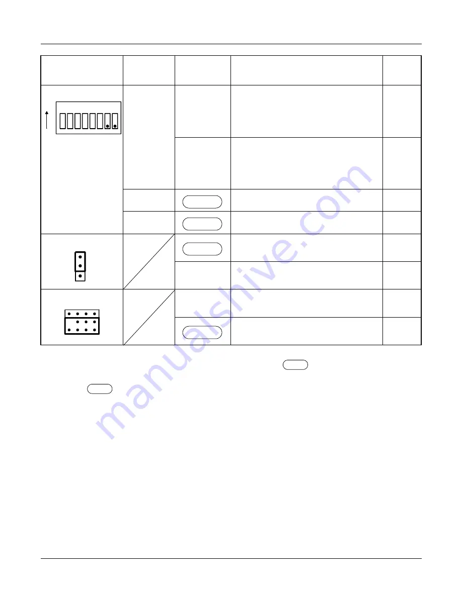
The figure in the SWITCH NAME column and the position in
in the SETTING POSITION
column indicate the standard setting of the switch. When the switch is not set as shown by the
figure and
, the setting of the switch varies with the system concerned.
NOTE 1: Set the groove on the switch to the desired position.
NOTE 2: When the power is on, flip the MB switch to ON (UP position) before plugging/unplug-
ging the circuit card.
NOTE 3: When the DCE connected to the port does not provide a function to send the DSR sig-
nals, set the switch to ON. In this case, the AP00 card cannot recognize the actual state
of the DCE, so that the call records or system messages will not be stored in the mem-
SW2 (DIP SW)
6
NOTE 4
ON
• Uses internal clock as the receive
clock when No. 1 Port is synchro-
nous.
• When No. 1 Port is asynchronous.
OFF
Enables receive clock from the DCE
(Modem) when No. 1 Port is syn-
chronous. (Clock is received at the
RXC terminal)
7
Not used
8
Not used
JP0 (Jumper SW)
For normal operation
(Memory backup ON)
DOWN
Not used
(Memory backup OFF)
JP1 (Jumper SW)
UP
Not used
For normal operation
SWITCH NAME
SWITCH
NUMBER
SETTING
POSITION
FUNCTION
CHECK
1 2 3 4 5 6 7 8
ON
OFF
OFF
UP
DOWN


