


CHAPTER 3 LAMP INDICATIONS AND SWITCH SETTINGS
PN-BRTA (BRT)
NEAX2000 IVS
2
Installation Procedure Manual
Page 240
ND-70928 (E), Issue 1.0
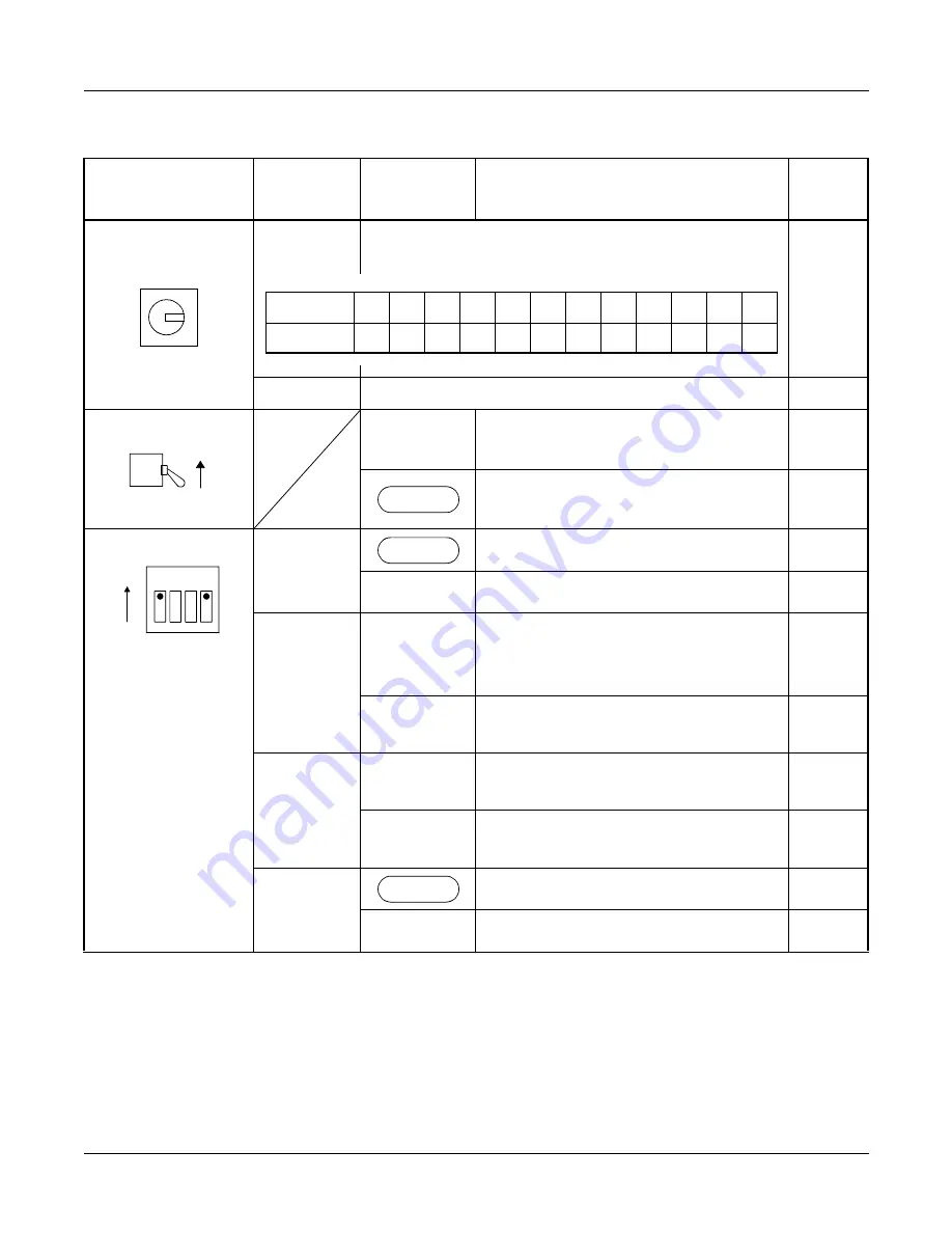
Switch Settings
SWITCH NAME
SWITCH
NUMBER
SETTING
POSITION
FUNCTION
CHECK
SENSE
(Rotary SW)
NOTE 1
4-F
Set the switch to match the AP Number (04-15) to
be set by CM05.
0-3
Not used
MB (Toggle SW)
NOTE 2
UP
For make-busy
For normal operation
SW0 (DIP SW)
1
For normal operation
OFF
Not used
2
NOTE 3
NOTE 4
ON
Source clock signal from network is
sent to the PLO of MP according to
the switch setting of SW0-3.
OFF
Source clock signal from network is
not sent to the PLO of MP card.
3
NOTE 3
NOTE 4
ON
Clock signal is sent to the PLO 0 of
MP.
OFF
Clock signal is sent to the PLO 1 of
MP.
4
For normal operation
OFF
Not used
(Continued)
AP No.
04 05 06 07 08 09 10 11 12 13 14 15
SW No.
4
5
6
7
8
9
A
B
C
D
E
F
ON
DOWN
1 2 3 4
ON
ON
ON


