CHAPTER 3 LAMP INDICATIONS AND SWITCH SETTINGS
PN-24DTA-C (DTI)
NEAX2000 IVS
2
Installation Procedure Manual
ND-70928 (E), Issue 1.0
Page 281
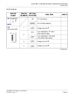
SW0
(Piano Key SW)
1
NOTE 3
NOTE 4
ON
Source clock signal from network is
sent to the PLO 0 input on MP card.
OFF
Source clock signal from network is
not sent to the PLO 0 input on MP
card.
2
NOTE 3
NOTE 4
ON
Source clock signal from network is
sent to the PLO 1 input on MP card.
OFF
Source clock signal from network is
not sent to the PLO 1 input on MP
card.
3
ON
Remote loop-back
For normal operation
4
ON
Local loop-back (AIS send)
For normal operation
5
Set equalizer according to the cable
length between the PBX and the
MDF.
OFF
6
OFF
7
OFF
8
Not used
(Continued)
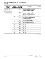
SWITCH NAME
SWITCH
NUMBER
SETTING
POSITION
FUNCTION
CHECK
OFF
ON
5
6
7
8
1
2
3
4
OFF
OFF
ON
OFF
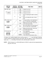
80-120m (262.5-394ft.)
SW0-5 SW0-6 SW0-7
CABLE LENGTH
ON
ON
0-40m (0-131.2ft.)
40-80m (131.2-262.5ft.)
120-160m (394-525ft.)
160-200m (525-656ft.)
Signal is not sent
ON
ON
ON
ON
ON
OFF
OFF
ON
OFF
ON
OFF ON
OFF
OFF OFF
ON
ON
OFF


