


CHAPTER 3 LAMP INDICATIONS AND SWITCH SETTINGS
PN-2ILCA (ILC)
NEAX2000 IVS
2
Installation Procedure Manual
Page 362
ND-70928 (E), Issue 1.0
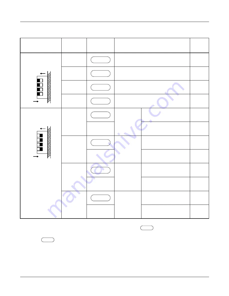
Switch Settings
The figure in the SWITCH NAME column and the position in
in the SETTING POSITION
column indicate the standard setting of the switch. When the switch is not set as shown by the
figure and
, the setting of the switch varies with the system concerned.
SWITCH NAME
SWITCH
NUMBER
SETTING
POSITION
FUNCTION
CHECK
SW1
(Piano Key SW)
1
Always set to OFF
2
Always set to OFF
3
Always set to OFF
4
Always set to OFF
SW0
(Piano Key SW)
1
No.0
Circuit
(Receiving)
Terminating register is
provided.
OFF
Terminating register is
not provided.
2
No.0
Circuit
(Sending)
Terminating register is
provided.
OFF
Terminating register is
not provided.
3
No.1
Circuit
(Receiving)
Terminating register is
provided.
OFF
Terminating register is
not provided.
4
No.1
Circuit
(Sending)
Terminating register is
provided.
OFF
Terminating register is
not provided.
4
3
2
1
OFF
ON
OFF
OFF
OFF
OFF
4
3
2
1
OFF
ON
ON
ON
ON
ON


