


CHAPTER 2 INSTALLATION
– 58 –
ND-71503(E) Rev.5.0
9pch2001.fm
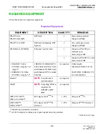
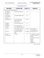
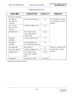
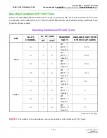
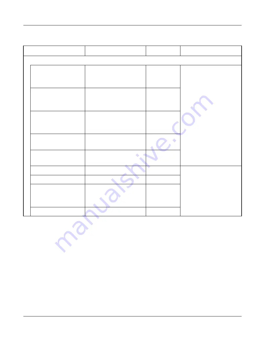
Required Equipment
*
: Should be provided by customer.
EQUIPMENT
DESCRIPTION
QUANTITY
REMARKS
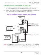
• For H.323 Connection
PN-32IPLA/
PN-32IPLA-A
(IP-PAD)
32-channel IP-PAD Card
1-8
For D
term
IP H.323 connec-
tion, IP-PAD card must be
installed.
PN-16VCTA /
PN-16VCTA-A
(16VCT)
16-channel CODEC Card
1-16
IPTRK BUS CA
Set of 3 BUS Cables
between IP-PAD and
16VCT Cards
1-8 sets
PN-8IPLA
(IP-PAD)
8-channel IP-PAD Card
1-8
PZ-24IPLA
(24DSP)
24-channel DSP Card
for 8-channel IP-PAD Card
1-8
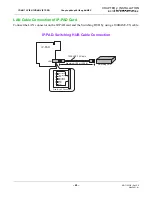
PN-IPTB (IPT)
IP Trunk Card
1-8
For H.323 connection, IPT
card and 4VCT card are
required.
PN-4VCTI (4VCT)
4-channel CODEC Card
1-32
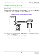
IPTRK BUS CA
Set of 3 BUS Cables
between IPT and 4VCT
Cards
1-8 sets
Gatekeeper
*
Gatekeeper for H.323
As required
JANUARY/16/2004
REQUIRED EQUIPMENT
CÔNG TY VIỄN THÔNG VIỆT PRO
Chuyên phân phối tổng đài NEC
http://vietpro.com.vn


