32
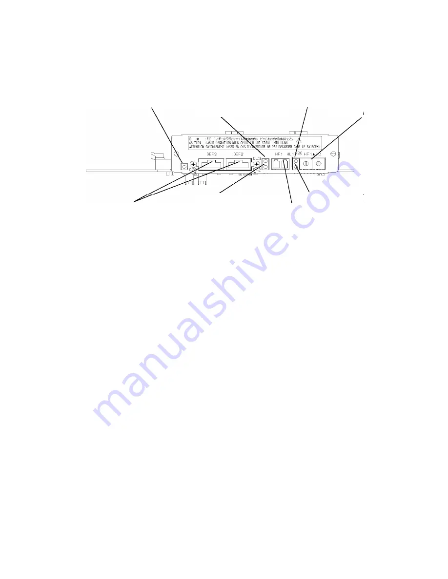
3.11 Additional Control Card
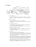
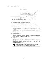
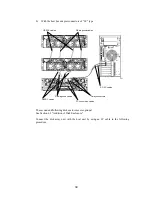
(1) FC connectors (for connection of disk enclosure) (DEF2/DEF3)
Each FC connector is used to connect the array controller with the disk enclosure.
See Section 5 "CONNECTION OF DISK ARRAY UNIT" for the cable connection.
(2) FC connector (for connection of host bus adapter) (HF1)
The FC connector is used to connect the host system with the disk array unit.
See Section 5 "CONNECTION OF DISK ARRAY UNIT" for the cable connection.
(3) LINKUP LEDs (DL2/DL3/HL1)
Each LINKUP LED lights green when the corresponding FC connector (FC port)
becomes operable (Link UP). DL2 LED corresponds to the DEF2 connector, DL3
LED corresponds to the DEF3 connector, and HL1 LED corresponds to the HF1
connector.
The LED is off during the self-test or initialization just after power-on.
(4) DISK-2G LED (green)
The DISK-2G LED lights green while the disk interface is operating at 2Gbps. The
LED is off while it is operating at 1Gbps.
(5) HOST-2G LED (green)
The HOST-2G LED lights green while the host bus adapter interface is operating at
2Gbps. The LED is off while it is operating at 1Gbps.
(4) DISK-2G LED (D2G)
(5) HOST-2G LED (H2G)
(3) LINKUP LED (DL3)
(1) FC connectors (for connection
of disk enclosure)
(6) AL-PA switch
(2) FC connector (for connection
of host bus adapter)
(3) LINKUP LED (DL2)
(3) LINKUP LED (HL1)
Summary of Contents for NF2300-SR412E
Page 7: ...v ...
Page 8: ...vi ...
Page 9: ...vii ...
Page 10: ...viii ...
Page 63: ...45 ...
Page 65: ...47 Sample configuration 2 NF2300 SR4xxE NF2300 SP02E ...

