64
(4) Settings
of
switches
a)
Setting of AL-PA switch on disk enclosure
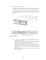
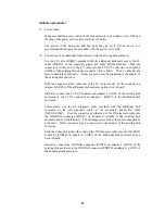
Set an AL-PA by using the AL-PA switch on each adapter of the additional
disk enclosure.
The AL-PA switches on both adapters are factory-set to "1". Set an AL-PA so
that it will be different from the AL-PAs of other disk enclosures in the same
FC loop.
Set "0" for the AL-PA switches on both adapters in the first disk enclosure that
is connected to the array controller via the FC cable (HSSDC). If you have
installed additional disk enclosures, set the AL-PA switches on both adapters of
each additional enclosure to "1", "2", ... "5", and then "6" in the connection
order.
If you set different values for the AL-PA switches on the right and left adapters
of an additional disk enclosure, the FAULT LED on each adapter flashes and
the disk enclosure fails to start. If you have set different values, turn off the
system including the additional disk enclosure, set the same value for the
AL-PA switches, and then turn on the power.
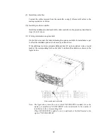
b) Setting of DE-DIAG ID switch on disk enclosure
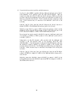
Set a DE-DIAG ID by using the DE-DIAG ID switch on each adapter of the
additional disk enclosure.
Set "0" for all the DE-DIAG IDs of the adapters installed in the disk enclosure
that is connected with the standard controller in the array controller via the FC
cable (HSSDC).
If an additional control card (NF2300-SP02E) is installed in the array
controller, set "1" for all the DE-DIAG IDs of the adapters installed in the disk
enclosure that is connected with the additional control card via the FC cable
(HSSDC).
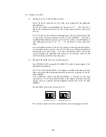
The DE-DIAG ID switch is factory-set to "0".
When DE-DIAG ID = "0"
When DE-DIAG ID = "1"
4 3 2 1
4 3 2 1 ON
ON
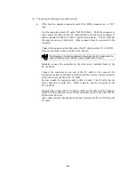
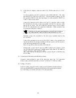
The set value of each switch on a disk enclosure is shown in pages 45 and 46.
Summary of Contents for NF2300-SR412E
Page 7: ...v ...
Page 8: ...vi ...
Page 9: ...vii ...
Page 10: ...viii ...
Page 63: ...45 ...
Page 65: ...47 Sample configuration 2 NF2300 SR4xxE NF2300 SP02E ...

