78
(6) Installation
of
cables
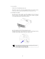
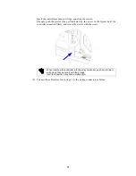
Connect the cables removed from the controller in step (2) Removal of cables to the
mating connectors as before.
(7) Installing in other controller
Install the cache memory in the other controller in the procedure described in steps
(2) to (6) above.
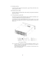
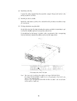
(8) Writing information on option label
On the disk array unit, the label indicating the options available for installation is put
to allow the installed options to be known by external view.
If the additional cache memory is added, write a round mark at the corresponding
field on the label to indicate the addition as shown in the figure below.
Write round mark as shown in the figure.
Note: The figure above indicates the addition of a single NF2300-SC01E.
If a single NF2300-SC02E is added, write a round mark at the field to the
right of "NF2300-SC02(E)".
If two or more NF2300-SC01E/NF2300-SC02E are added, write round marks
by the number of additions.
Summary of Contents for NF2300-SR412E
Page 7: ...v ...
Page 8: ...vi ...
Page 9: ...vii ...
Page 10: ...viii ...
Page 63: ...45 ...
Page 65: ...47 Sample configuration 2 NF2300 SR4xxE NF2300 SP02E ...

