Page 8
Important Information
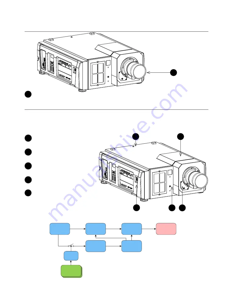
Location of laser aperture
1
Laser aperture
Interlock switches
Five interlock switches installed at the main frame, inside the cover, will power-off the system
individually when activated.
Location
1
Will be activated when the
top cover is removed.
2
Will be activated when the
lens is removed.
3
Will be activated when the
side cover is removed.
4
x2. Will be activated when
the front cover is removed.
5
Will be activated when
the lens access cover is
removed.
Interlock switch control block diagram
1
1
2
3
4
5
POWER
SUPPLY
DC-DC
Converter
Laser
Driver
Micro-
Controller
DC-DC
Regulator
Laser
Diodes
Interlock
Switch
OR
54 V
12 V
5 V


