background image

2

Please heed the following

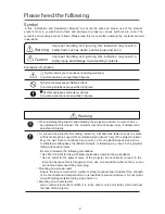
In this “Installation and Adjustment Manual”, to ensure the safe and proper use of the product,

prevent harm to yourself and others and damage to property, various symbols are used. The
symbols and meanings are as follows. Please read this manual after ensuring the contents are well
understood.

Improper handling and ignoring this indication may result in
bodily harm such as death, serious injury and so on.

Improper handling and ignoring this indication may result in
bodily injury and damage to surrounding contents.

Warning

Warning

Caution

Examples of symbols:

Symbol alerts you to cautions (including warnings)

Concrete cautions are specified in figures.

Symbol expresses prohibited actions

Concrete prohibitions are specified in figures.

Symbol expresses compulsory actions.

Concrete instructions are specified in figures.

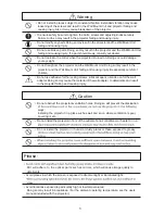
When installing the projector and adjusting the projection position, be sure to do so

as explained in this manual. The projector may fall and cause injury if installed and

adjusted improperly.

To prevent the projector from falling, install it in a location and fasten it so as to ensure

sufficient strength to support the combined weight (about 13 kg) of the projector (about

4kg), the wall mount unit (about 9 kg) and so on for an extended period as well as

to withstand earthquakes. Insufficient strength or fastening may result in the projector

falling and causing injury.
Be sure to observe the following precautions:

* Use M6 (1/4 inch) for the wall fixation bolts and screws for the wall adapter.

* Use an outlet for the power source of the projector. Do not directly connect to the

lamp line because this is dangerous. Also, use an accessible outlet so that you can

connect and disconnect the power plug.

Mounting on a wooden wall

Ensure the load is mounted on a pillar or robust constructional material. If the strength

of the constructional material and so on is insufficient, please reinforce it. Do not mount

on wall finishing material, furring strip and so on.

Mounting on a concrete wall

Use a commercial anchor bolt M6 (1/4 inch), anchor nuts and similar, which will bear

the load of the projector.

Symbol

Summary of Contents for NP03WK

Page 1: ...Wall Mount Unit NP02WK NP03WK Installation and Adjustment Manual...

Page 2: ...are required to install the pojector This work should never be performed by the customer To the Dealer and Installer be started after careful attention is paid to the strength of the mounting location...

Page 3: ...ctor may fall and cause injury if installed and adjusted improperly To prevent the projector from falling install it in a location and fasten it so as to ensure sufficient strength to support the comb...

Page 4: ...the wall adapter Doing somaycause the material of the wall adapter to deteriorate and result in the projector falling and causing injury Caution Do not obstruct the projector s ventilation holes Doing...

Page 5: ...K or NP03WK Wall adapter 1 Projector adapter 1 M5 screws 4 2 1 2 To be used when mounting the wall adapter in the North America region Cover A B 2 pairs Arm cover 1 Plate B 1 M4 20 screws 4 M3 5 9 4 s...

Page 6: ...on knobs Cover B A Wall adapter Covers A B Elongate hole for screw or bolt 4 parts Plate A Arm fixation screw Arm cover Plate B Horizontal adjust screws Horizontal fixation nut Projector fixation plat...

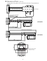
Page 7: ...ter are 142 100 100 142 100 100 189 90 190 189 219 490 850 Projector bottom surface including the legs 885 minimum 1245 maximum The center of the wall adapter central axis Dimensions of Parts unit mm...

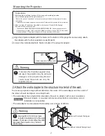
Page 8: ...adjusted horizontally over a range of 50mm Side with cutouts facing up Side without cutouts facing down Warning If screws other than the supplied ones Mounting the Projector Use only M6 1 4 inch scre...

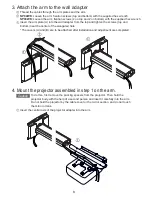
Page 9: ...hten the screws top and bottom near the center of the elongated hole The covers A and B are to be attached after installation and adjustment are completed 4 Mount the projector assembled in step 1 on...

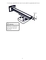
Page 10: ...e the two supplied M5 5x9 5 screws to securely attach the supplied plate B to the arm Warning If plate B is not installed the projector may slide out of the arm and fall off which may cause injury Pla...

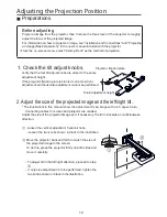
Page 11: ...ge and the left right tilt The illustrations in this manual show the adjustment for an image with a 4 3 aspect ratio Connecting cables for screen and projector are omitted Adjust the size of the proje...

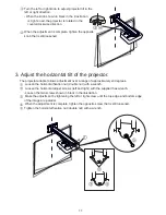
Page 12: ...rees Loosen the horizontal fixation nut double nut with a wrench Loosen the horizontal adjust screws left and right with the supplied hex wrench Loosen the two screws shown in black in the illustratio...

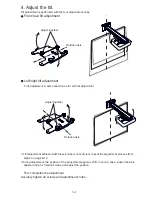
Page 13: ...djustment achieved with these knobs is not suf cient repeat the adjustment process from step 2 on page E 12 During adjustment the position of the projected image may shift In such a case loosen the wa...

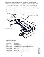
Page 14: ...the positions of covers A and B and attach them in the same way as described in r e v o c m r a e h t h c a t t A The cover is fixed when the left and right tabs engage with the notches on the projec...

Reviews: