


CHAPTER 12 REAL-TIME OUTPUT FUNCTION (RTO)
User’s Manual U16896EJ2V0UD
358
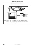
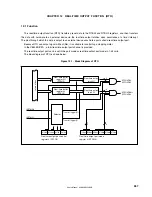
12.2 Configuration
RTO consists of the following hardware.
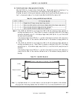
Table 12-1. Configuration of RTO
Item Configuration
Registers Real-time
output
buffer register 0 (RTBL0, RTBH0)
Control registers
Real-time output port mode register 0 (RTPM0)
Real-time output port control register 0 (RTPC0)
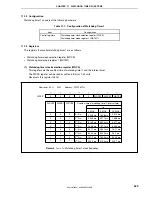
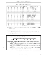
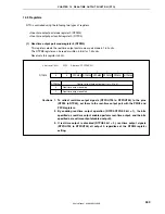
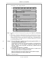
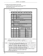
(1) Real-time output buffer register 0 (RTBL0, RTBH0)
RTBL0 and RTBH0 are 4-bit registers that hold output data in advance.
These registers are mapped to independent addresses in the peripheral I/O register area.
They can be read or written in 8-bit or 1-bit units.
If an operation mode of 4 bits
×
1 channel or 2 bits
×
1 channel is specified (RTPC0.BYTE0 bit = 0), data can
be individually set to the RTBL0 and RTBH0 registers. The data of both these registers can be read at once
by specifying the address of either of these registers.
If an operation mode of 6 bits
×
1 channel is specified (BYTE0 bit = 1), 8-bit data can be set to both the RTBL0
and RTBH0 registers by writing the data to either of these registers. Moreover, the data of both these
registers can be read at once by specifying the address of either of these registers.
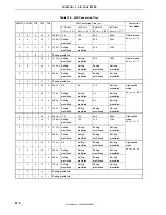
Table 12-2 shows the operation when the RTBL0 and RTBH0 registers are manipulated.
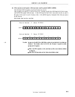
0
RTBL0
RTBH0
0
RTBH05 RTBH04
RTBL03
RTBL02
RTBL01
RTBL00
After reset: 00H R/W Address: RTBL0 FFFFF6E0H, RTBH0 FFFFF6E2H
Cautions 1. When writing to bits 6 and 7 of the RTBH0 register, always write 0.
2. Accessing the RTBL0 and RTBH0 registers is prohibited in the
following statuses. For details, refer to 3.4.8 (1) (b) Access to
special on-chip peripheral I/O register.
•
When the CPU operates on the subclock and the main clock oscillation is
stopped
•
When the CPU operates on the internal oscillation clock
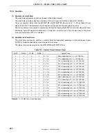
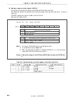
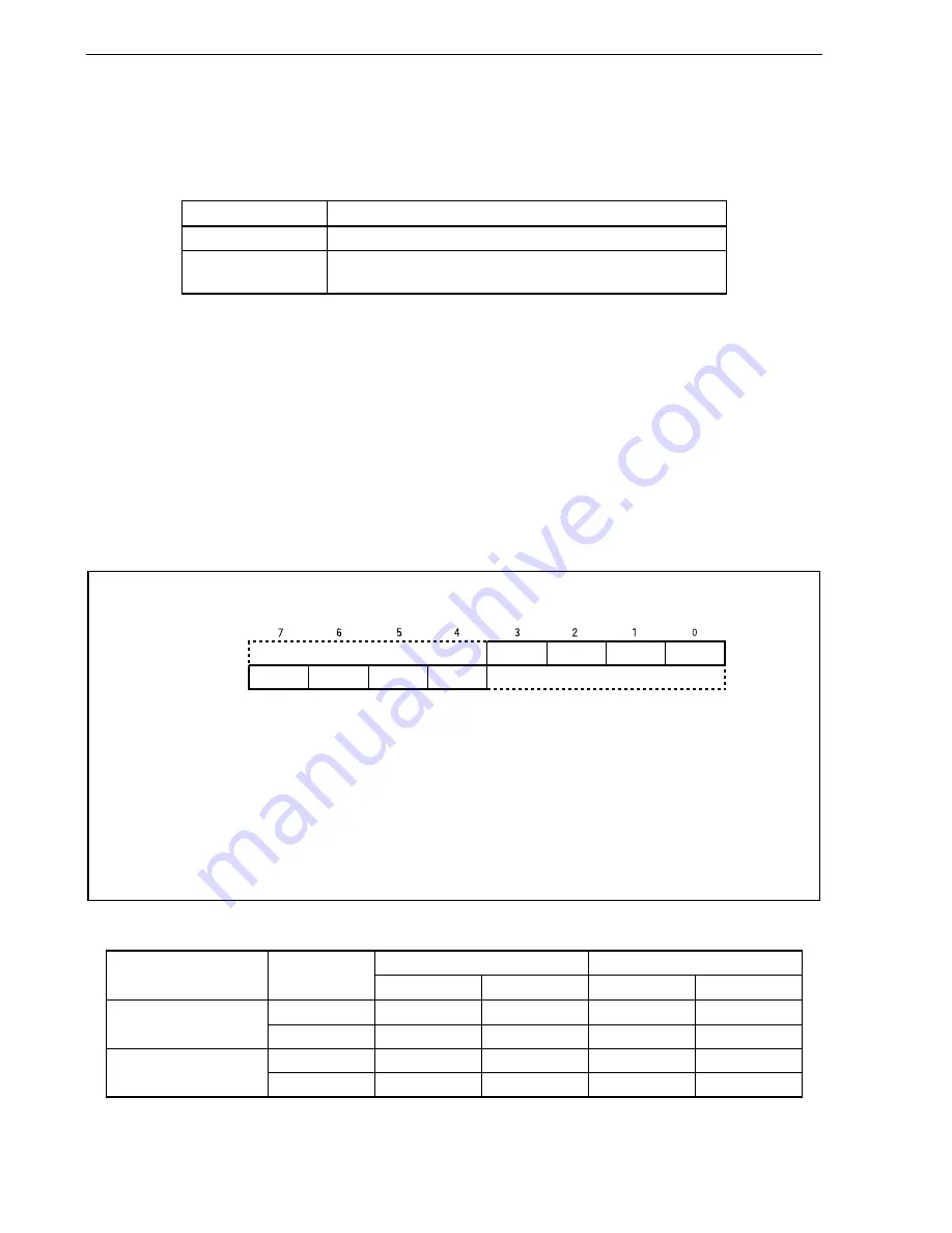
Table 12-2. Operation During Manipulation of RTBL0 and RTBH0 Registers
Read Write
Note
Operation Mode
Register to Be
Manipulated
Higher 4 Bits
Lower 4 Bits
Higher 4 Bits
Lower 4 Bits
RTBL0 RTBH0 RTBL0 Invalid RTBL0
4 bits
×
1 channel, 2 bits
×
1 channel
RTBH0 RTBH0 RTBL0 RTBH0 Invalid
RTBL0 RTBH0 RTBL0 RTBH0 RTBL0
6 bits
×
1 channel
RTBH0 RTBH0 RTBL0 RTBH0 RTBL0
Note
After setting the real-time output port, set output data to the RTBL0 and RTBH0 registers by the time a real-
time output trigger is generated.
<R>


