background image

CHAPTER  2   HARDWARE  INSTALLATION 

User’s Manual  U17454EJ1V0UM 

13

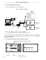
Target cable connector: 

Used to connect the connector of the target cable. 

USB connector: 


Used to connect the USB cable to be connected to the host machine. 

Power LED: 


Turned on in green when the FPL3 is connected to the host machine. 

Status LED: 


Blinks in red when the FPL3 is communicating with the target device. 


Caution  When the Status LED is blinking, communication with the target device is in progress.  Do not 

disconnect the target cable and USB cable. 
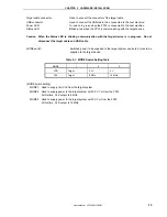
 

MODE switch: 

Switches power to be supplied to the target system and sets a clock to be 

supplied to the target device. 


Table 2-1.  MODE Switch Setting Table 

MODE 1 

VDD 

Target 

3.3 V 

5 V 

CLK 

Target 

8 MHz 

16 MHz 


[MODE switch setting] 

MODE1:  Used to supply V

DD

/CLK from the target system. 

MODE2:  Used to supply power to the target system with 3.3 V V

DD

 from the FPL3. 


At this time, CLK output is 8 MHz. 

MODE3:  Used to supply power to the target system with 5 V V

DD

 from the FPL3. 


At this time, CLK output is 16 MHz. 


Summary of Contents for PG-FPL3

Page 1: ...Document No U17454EJ1V0UM00 1st edition Date Published March 2005 N CP K Printed in Japan 2005 User s Manual PG FPL3 Flash Memory Programmer ...

Page 2: ...User s Manual U17454EJ1V0UM 2 MEMO ...

Page 3: ...vors to enhance the quality reliability and safety of NEC Electronics products customers agree and acknowledge that the possibility of defects thereof cannot be eliminated entirely To minimize risks of damage to property or injury including death to persons arising from defects in NEC Electronics products customers must incorporate sufficient safety measures in their design such as redundancy fire...

Page 4: ... connection was in an unsatisfactory state If the USB cable target cable or the like was bent or pulled excessively If the product got wet If the product and target system were connected while a potential difference existed between the GND of the product and the GND of the target system If a connector or cable was removed while the power was being supplied to the product If an excessive load was p...

Page 5: ...anch Seoul Korea Tel 02 558 3737 NEC Electronics Shanghai Ltd Shanghai P R China Tel 021 5888 5400 NEC Electronics Taiwan Ltd Taipei Taiwan Tel 02 2719 2377 NEC Electronics Singapore Pte Ltd Novena Square Singapore Tel 6253 8311 J04 1 NEC Electronics Europe GmbH Duesseldorf Germany Tel 0211 65030 Sucursal en España Madrid Spain Tel 091 504 27 87 Vélizy Villacoublay France Tel 01 30 67 58 00 Succur...

Page 6: ...s the following sections Overview Hardware installation Software installation Operation using GUI software Usage examples Connectors and cables Notes on target system Circuit diagrams Troubleshooting How to Read This Manual To understand the overall functions and usage of the PG FPL3 read this manual in the order of the CONTENTS Be sure to read CHAPTER 4 OPERATION USING GUI SOFTWARE because this c...

Page 7: ... using GUI software Target device NEC Electronics on chip flash memory microcontroller Target system User designed board on which NEC Electronics on chip flash memory microcontroller is mounted FP4 connector Abbreviation of PG FP4 target connector type A FA adapter Adapter board to write programs to NEC Electronics on chip flash memory microcontroller Note 78K0 Kx2 Generic name of 78K0 KB2 78K0 KC...

Page 8: ...18 3 1 GUI Software Installation 18 3 2 Driver Installation 23 3 2 1 Installation in Windows 98 Me 23 3 2 2 Installation in Windows 2000 26 3 2 3 Installation in Windows XP 32 3 3 Confirmation of USB Driver Installation 36 3 4 Uninstallation 37 3 4 1 Driver uninstallation 37 3 4 2 GUI software uninstallation 38 CHAPTER 4 OPERATION USING GUI SOFTWARE 40 4 1 Introduction 40 4 2 Starting up GUI Softw...

Page 9: ... CHAPTER 7 NOTES ON TARGET SYSTEMS 67 CHAPTER 8 CIRCUIT DIAGRAMS 70 CHAPTER 9 TROUBLESHOOTING 72 9 1 Trouble During Setup 72 9 2 Trouble During Operation Main Unit 73 9 3 Trouble During Operation Communication 74 APPENDIX A PRODUCT SPECIFICATIONS 76 A 1 Hardware Specifications 76 A 2 Dimensions 77 APPENDIX B WARRANTY AND SUPPORT 80 B 1 Warranty 80 B 2 Support 80 ...

Page 10: ...L3 is a compact flash memory programmer for an on chip flash memory microcontroller and is designed for development The USB interface is available for connection with the host The PG FPL3 allows on board programming without removing the target device from the target system Only UART interface is supported for data transfer to the target device Device specific parameters required for programming ca...

Page 11: ...chine IBM PC ATTM or compatible CPU PentiumTM 100 MHz or more RAM 32 MB or more Host interface USB interface that enables communication based on USB Ver 1 1 or later File formats Program files can be used in Motorola HEX file format or Intel HEX file format 2 2 Package Contents Please verify that you have received all the parts listed in the package contents list included with the FPL3 package If ...

Page 12: ... cable Mini B type included with the IECUBE 2 The FA adapter board is a product of Naito Densei Machida Mfg Co Ltd The FPL3 is connected to the host machine via the USB cable Mini B type The FPL3 is connected to the user system via the target cable For the detailed specifications of the target cable and connector refer to CHAPTER 6 CONNECTORS AND CABLES 2 3 1 FPL3 display specifications connector ...

Page 13: ...inking communication with the target device is in progress Do not disconnect the target cable and USB cable MODE switch Switches power to be supplied to the target system and sets a clock to be supplied to the target device Table 2 1 MODE Switch Setting Table MODE 1 2 3 VDD Target 3 3 V 5 V CLK Target 8 MHz 16 MHz MODE switch setting MODE1 Used to supply VDD CLK from the target system MODE2 Used t...

Page 14: ... must be equipped with a device interface that complies with the target cable specifications Refer to CHAPTER 6 CONNECTORS AND CABLES for details 2 3 4 USB connector The shape of the USB connector is a Mini B type Refer to CHAPTER 6 CONNECTORS AND CABLES for details 2 3 5 Target cable The tip of the target cable can be connected to the header pin that is 0 635 mm by 0 635 mm Refer to CHAPTER 6 CON...

Page 15: ...to perform this step before making a connection with the target system If connections are made in an incorrect order the FPL3 and target system may be damaged 2 When the MODE switch is set to MODE2 or MODE3 power is supplied from the FPL3 the voltage set to the VDD pin is output when the FPL3 is connected with the host machine 3 Connect the target system with the FPL3 follow either setting a or b ...

Page 16: ...tem 4 Be sure to turn on the power to the target system When the MODE switch is set to MODE2 or MODE3 power is supplied from the FPL3 so this step is not required b When the FPL3 is connected with the target system without using the FPL3 FA 1 Disconnect the FPL3 FA from the target cable 2 Make sure that the power to the target system is not turned on Caution Make sure that the power to the target ...

Page 17: ...ower is supplied from the FPL3 so this step is not required 2 Disconnect the FPL3 FA from the target system Caution When the MODE switch is set to MODE2 or MODE3 the FPL3 outputs power at all times Be sure to disconnect the FP4 connector from the target system before disconnecting the target device b When the FPL3 is connected with the target system without using the FPL3 FA 1 Turn off the power t...

Page 18: ...ows XP log on as the computer administrator When using Windows 2000 log on as the Administrator 2 Insert the CD ROM IECUBE Accessory Disk included with the IECUBE package into the CD ROM drive 3 Double click My Computer CD ROM PG FPL3 and SETUP in that order Double click setup exe in the SETUP folder 4 Select a language to be used for installation English in this example then click OK Figure 3 1 S...

Page 19: ...g the PG FPL3 If you do not accept the agreement click No to terminate the installation of the software Figure 3 3 License Agreement Window 7 Check that Typical is selected then click Next Figure 3 4 Setup Type Remark By selecting Custom only the GUI software or document can be installed The GUI software installation destination can be changed by clicking Browse This manual assumes the default ins...

Page 20: ...lation folder and then click OK Figure 3 5 Changing Installation Folder When Custom is clicked Select the check box of the item to be installed and then click Next Figure 3 6 Custom Installation Check here when installing documents Click after confirming the check boxes Check here when installing the GUI software Specify an installation destination folder path ...

Page 21: ...s Manual U17454EJ1V0UM 21 8 Specify or select the program folder and then click Next Figure 3 7 Program Folder Selection 9 Confirm the current setting and then click Next Program installation starts Figure 3 8 Start of File Copy Operation ...

Page 22: ...Installation 11 The following folders are created upon completion of installation Figure 3 10 Folder Configuration After Installation C Program Files NECTools32 bin PRM doc PG FPL3 FPL3 exe FPL3ctl dll DRIVER Ftdiunin exe Other driver related files PG FPL3 PG FPL3_UM_E pdf FTDI Folder specified as the installation destination PRM file storage folder GUI software This manual Driver uninstallation e...

Page 23: ... Me Installation in Windows 2000 See 3 2 2 Installation in Windows 2000 Installation in Windows XP See 3 2 3 Installation in Windows XP 3 2 1 Installation in Windows 98 Me 1 When the FPL3 is connected with the host machine the FPL3 is recognized by Plug and Play and the wizard for adding new hardware is started 2 The window below is displayed Check that Specify the location is selected then click ...

Page 24: ... Next Figure 3 12 Search Location Specification Windows Me Remark If the installation destination folder is changed for GUI software installation enter new folder bin PG FPL3 DRIVER FTDI 4 The window below is displayed Confirm the contents and click Next Figure 3 13 Checking Driver to Be Installed Windows Me 1 Check Specify a location only 2 Enter C Program Files NECTools32 bin PG FPL3 DRIVER FTDI...

Page 25: ...U17454EJ1V0UM 25 5 When installation of the USB driver is complete the screen shown below appears Click Finish Subsequently the installation of the USB Serial Port driver is automatically performed Figure 3 14 Completion of Installation Windows Me ...

Page 26: ...ine the FPL3 is recognized by Plug and Play and the wizard for finding new hardware is started Click Next Figure 3 15 Found New Hardware Wizard Windows 2000 2 The window below is displayed Check that Search for a suitable driver is selected then click Next Figure 3 16 Search Method Windows 2000 Check that Search for a suitable driver is selected ...

Page 27: ...0 4 Enter C Program Files NECTools32 bin PG FPL3 DRIVER FTDI in the address bar then click OK Figure 3 18 Address Specification Windows 2000 Remark If the installation destination folder is changed for GUI software installation enter new folder bin PG FPL3 DRIVER FTDI Check that Specify a location only is checked Enter C Program Files NECTools32 bin PG FPL3 DRIVER FTDI ...

Page 28: ...ck Next Figure 3 19 Driver File Search Windows 2000 6 When installation of the USB driver is complete the screen shown below appears Click Finish to complete installation When installation is complete restart the computer following the instructions as restart is requested Figure 3 20 USB Driver Installation Completion Windows 2000 ...

Page 29: ...of the USB Serial Port driver is started Click Next Figure 3 21 Found New Hardware Wizard 2 Windows 2000 8 The window below is displayed Check that Search for a suitable driver is selected then click Next Figure 3 22 Search Method 2 Windows 2000 Check that Search for a suitable driver is selected ...

Page 30: ... 10 Enter C Program Files NECTools32 bin PG FPL3 DRIVER FTDI in the address bar then click OK Figure 3 24 Address Specification 2 Windows 2000 Remark If the installation destination folder is changed for GUI software installation enter new folder bin PG FPL3 DRIVER FTDI Check that Specify a location only is checked Enter C Program Files NECTools32 bin PG FPL3 DRIVER FTDI ...

Page 31: ...is searched and the window below is displayed Click Next Figure 3 25 Driver File Search 2 Windows 2000 12 When installation of the USB driver is complete the screen shown below appears Click Finish to complete installation Figure 3 26 USB Driver Installation Completion 2 Windows 2000 ...

Page 32: ... Play and the wizard for finding new hardware is started Check that No not this time is selected then click Next Figure 3 27 Found New Hardware Wizard Windows XP 2 Check that Install from a list or specific is selected then click Next Figure 3 28 Installation Method Selection Windows XP Check that Install from a list or specific is selected Check that No not this time is selected ...

Page 33: ...ch Method Windows XP Remark If the installation destination folder is changed for GUI software installation enter new folder bin PG FPL3 DRIVER FTDI 4 When installation of the USB driver is complete the screen shown below appears Click Finish to complete installation Figure 3 30 USB Driver Installation Completion Windows XP 2 Check Include this location in the search only 3 Enter C Program Files N...

Page 34: ...ding new hardware is started Check that No not this time is selected then click Next Figure 3 31 Found New Hardware Wizard 2 Windows XP 6 Check that Install from a list or specific is selected then click Next Figure 3 32 Installation Method Selection Windows XP Check that Install from a list or specific is selected Check that No not this time is selected ...

Page 35: ...d 2 Windows XP Remark If the installation destination folder is changed for GUI software installation enter new folder bin PG FPL3 DRIVER FTDI 8 When installation of the USB driver is complete the screen shown below appears Click Finish to complete installation Figure 3 34 USB Serial Port 2 Driver Installation Completion Windows XP 2 Check Include this location in the search only 3 Enter C Program...

Page 36: ...rmally Figure 3 35 Device Manager Cautions 1 When using the FPL3 in Windows 98 Me do not select Refresh or Remove when communicating with the target device 2 When using the FPL3 in Windows 2000 XP do not perform Scan for hardware changes when communicating with the target device Remarks 1 Select the same communication port as COM for the USB Serial Port COM in the GUI Port list box 2 If the driver...

Page 37: ...rator 2 Double click My Computer C Program Files NECTools32 bin PG FPL3 DRIVER and FTDI in that order Double click Ftdiunin exe in the FTDI folder 3 Uninstaller starts so click Continue Figure 3 36 Driver Uninstaller 4 When uninstallation of the USB driver is complete the screen shown below appears Click Finish to complete uninstallation of the driver Figure 3 37 Driver Uninstallation Completion C...

Page 38: ...Windows XP log on as the computer administrator When using Windows 2000 log on as the Administrator 2 Insert the CD ROM IECUBE Accessory Disk included with the IECUBE package into the CD ROM drive 3 Double click My Computer CD ROM PG FPL3 and SETUP in that order Double click setup exe in the SETUP folder 4 Select a language to be used for installation English in this example then click OK Figure 3...

Page 39: ...54EJ1V0UM 39 6 Click OK to start uninstallation Figure 3 40 Confirmation of File Deletion 7 When uninstallation of the GUI software is complete the screen shown below appears Click Finish to complete uninstallation Figure 3 41 Completion of Maintenance ...

Page 40: ...l website in English http www necel com micro ods jpn index html website in Japanese The PRM file downloaded from the NEC Electronics website must be copied into the sub directory FPL3 EXE installation path PRM which was created during GUI software setup see CHAPTER 3 SOFTWARE INSTALLATION 4 2 Starting up GUI Software GUI software startup Select FPL3 EXE in the Start menu to start the FPL3 GUI sof...

Page 41: ... right of the action log window Displays programming parameter settings Status bar Displays status 4 3 Toolbar The toolbar contains buttons to start the most important procedures of the FPL3 Table 4 1 Toolbar Buttons Device Setup button File Load button Device Blank check button Device Erase button Device Program button Device Verify button Device Autoprocedure EPV button 4 4 Menus Depending on th...

Page 42: ...rogram the checksum is calculated and the result is displayed in the programmer parameter window Open button Selects a user program as a program to be written to the target device Cancel button Closes the window without selecting a program 2 Quit command The Quit command terminates the FPL3 GUI software Clicking the X button on the right side of the task bar also terminates the FPL3 GUI software U...

Page 43: ...he target device before starting programming 2 Erase command The Erase command initiates the erase procedure for the target device connected to the FPL3 While erasing the contents in the flash memory is in progress the progress is displayed in the action log window indicating the operation of the programmer The Blank Check command that is executed before the Erase command is executed in accordance...

Page 44: ...target device command execution result 5 Security command The Security command initiates the programming of the security flag of the target device connected to the FPL3 Set Security flag settings on the Advance tab of the Device Setup menu 6 CheckSum command The CheckSum command initiates the reading of the checksum values of the target device connected to the FPL3 This value differs from the valu...

Page 45: ... specify any additional security Figure 4 5 Device Setup Window Advance Tab 10 Setup command The Setup command is used to perform flash memory writing settings in accordance with the user environment and command option settings Each time the GUI software is started the parameter file PRM and customized setup file SET that were used last are read and their setting contents are displayed Settings ca...

Page 46: ... be set in accordance with the user environment and target device OK button Saves the settings in the Standard and Advance tabs and closes the window Cancel button Closes the window without saving the settings in the Standard and Advance tabs 1 Parameter file This file holds parameters and timing data required to rewrite the flash memory of the target device Do not modify the data in the parameter...

Page 47: ...arget device and host machine in this area Figure 4 9 Device Setup Window Host Connection Port box Displays the communication channel between the FPL3 and host machine COM1 to COM256 Remark The selectable port can be checked with the Device Manager For details refer to 3 3 Confirmation of USB Driver Installation Speed box Displays the communication rate of the communication channel 115 200 bps Rem...

Page 48: ...sion rate or multiplication rate varies depending on the device set it by checking the device specifications If the target device does not include the PLL circuit select 1 0 The default setting is displayed by the parameter file in the initial screen 4 Operation Mode The flash memory may be divided into blocks or areas depending on the target device This menu is used to select the operation mode o...

Page 49: ...ifies whether numbers or addresses are displayed in the Start End list boxes If this check box is checked addresses are displayed If it is not checked numbers are displayed 5 Target Reset Message By checking the Target Reset Message check box the window promoting the reset operation manually is displayed even when the reset signal cannot be connected to the target cable Figure 4 12 Device Setup Wi...

Page 50: ...this area Figure 4 14 Device Setup Window Command Options Blank check before Erase check box If this check box is checked a blank check is performed before execution of the Erase and Autoprocedure EPV commands If the result of the blank check is OK erase processing is not executed Read verify after Program check box If this check box is checked the written data is transmitted from the programmer a...

Page 51: ...g settings The Security flag settings dialog box is used to specify which security function is valid Figure 4 15 Device Setup Window Security Flag Settings Caution The following is the correspondence between the Erase and Program commands when the security functions of a 78K0 Kx2 Series microcontroller are valid Chip Erase Command Block Erase Command Program Command Disable Chip Erase Invalid Inva...

Page 52: ...ared by the Erase command when Chip was selected under Operation Mode Disable Program check box If this check box is checked the Program command becomes invalid as does the Erase command in all the blocks of the flash memory selected under Operation Mode in the Standard Setup menu The Erase command for the entire flash memory area is valid This setting is cleared by the Erase command when Chip was...

Page 53: ...eset Message Remark The Target Reset Message check box is common to Standard and Advance tabs 4 4 3 View menu Clicking the View menu displays the following pull down menu This menu consists of commands for setting whether to display the toolbar and status bar Figure 4 19 View Menu 1 Toolbar command Checking the Toolbar command displays the toolbar Unchecking the command hides the toolbar 2 Status ...

Page 54: ... 4 4 Help menu Clicking the Help menu displays the following pull down menu Figure 4 20 Help Menu 1 About FPL3 command The About FPL3 command opens the following program entry window and indicates the version Clicking OK terminates the display Figure 4 21 About FPL3 Window ...

Page 55: ...Window Device Displays information about a target device updated after communication with the target device Parameter file Displays information about a parameter file updated and read after Setup command execution Load file Selects information about a program file updated and selected after Load command execution Connection to device Displays information about the connection with the target device...

Page 56: ... Port COM5 115 200 bps MODE switch 3 VDD 5 V CLK 16 MHz Operation mode Chip Write HEX FPL3_TEST HEX Option setting Blank check before Erase Read Verify after Program 1 Installing the GUI software Install the FPL3 GUI software in the host machine you are using by referring to CHAPTER 3 SOFTWARE INSTALLATION if the software has not been installed yet 2 Installing the driver Install the USB driver in...

Page 57: ...r LED is turned on 4 Check that the power to the target system is not turned on then connect the FPL3 with the target system via the target cable 5 Start the GUI software Figure 5 1 GUI Software Main Window 5 Setting the programming environment 1 Select Device Setup from the menu bar 2 The Standard tab of the Device Setup window for device setup is activated Figure 5 2 Device Setup Window Standard...

Page 58: ...k Open Figure 5 3 Parameter File Selection 4 Set the items in the Operation Mode field so that the FPL3 is adjusted to the user programming environment Here assume that the settings shown below are set Figure 5 4 Device Setup Window Standard Tab After Setting Remark The selectable port can be checked with the Device Manager For details refer to 3 3 Confirmation of USB Driver Installation ...

Page 59: ...454EJ1V0UM 59 5 Switch to the Advance tab Figure 5 5 Device Setup Window Advance Tab Command options Blank check before Erase Checked Read verify after Program Checked Security flag after Program Not checked Checksum after Program Not checked ...

Page 60: ...Manual U17454EJ1V0UM 60 6 Click OK The GUI software sets the parameters When the settings are completed the following screen is displayed Figure 5 6 Completion of Parameter Setting PRM File Read OK is displayed Parameters are updated ...

Page 61: ...Device Autoprocedure EPV from the menu bar When the Autoprocedure EPV command is executed Erase Program are executed sequentially for the µPD78F0533 In this example Blank check before Erase and Read verify after Program are checked So blank check is performed before the execution of the Autoprocedure EPV command and read verify is performed after the execution of the Autoprocedure EPV command Para...

Page 62: ...Quit to terminate the GUI software All settings executed so far are saved in the FPL3 INI file so that those settings can be reused when the GUI software is restarted 2 Disconnect the target cable from the target system 3 Disconnect the USB cable from the FPL3 9 Restart When the system is restarted the same screen as shown in Figure 5 6 appears finish is displayed ...

Page 63: ... Power Supply Connector 1 5 Table 6 1 Pin Assignment of USB Connector USB Connector FPL3 Signal Name 1 5 V 2 DM 3 DP 4 N C 5 GND Connector part number UX60A MB 5ST made by Hirose Electric Remark The recommended USB cable Mini B type for connection with the host machine is the USB cable included with the IECUBE ...

Page 64: ...e by Hirose Electric 6 3 Target Cable Specifications Figure 6 3 External View of Target Cable Table 6 3 Pin Assignment of Target Cable Cable Specification Display Specification No 1 Black GND 0 GND No 2 Brown VDD 1 VDD No 3 Red CLK 2 CLK No 4 Orange RESET 3 RESET No 5 Yellow TxD 4 TXD No 6 Green RxD 5 RXD No 7 Blue FLMD0 6 FLMD0 Supported header pin specification 0 635 0 635 mm length 6 mm Remark ...

Page 65: ...MD0 Connector part number FFC 7AMEP1 made by Honda Tsushin Kogyo 6 5 FP4 Connector FPL3 FA Figure 6 5 External View of FP4 Connector Table 6 5 Pin Assignment of FP4 Connector FP4 Connector FPL3 FA Signal Name 1 GND 2 RESET 3 RxD 4 VDD 5 TxD 9 CLK 14 FLMD0 6 7 8 10 11 12 13 15 16 N C Connector part number 8516 4500PL made by Sumitomo 3M Remark The recommended receptacle connector that can be used w...

Page 66: ...nnections Signal Name 1 Target Cable Connector 2 Tip of Target Cable 3 Target Connector 4 FP4 Connector GND 1 0 GND 0 1 RESET 4 1 VDD 1 2 RxD 6 2 CLK 2 3 VDD 2 3 RESET 3 4 TxD 5 4 TXD 4 5 CLK 3 5 RXD 5 9 FLMD0 7 6 FLMD0 6 14 Figure 6 6 Target Interface 1 2 3 PG FPL3 Status Power MODE Target Target cable FPL3 FA PG FPL3 1 2 3 4 ...

Page 67: ...SET signal of the FPL3 Do not generate RESET while the FPL3 is connected This must be especially noted in a system that uses an external watchdog timer RESET Connect the RESET signal of the FPL3 at a point where the status of the programmer RESET signal and that of the CPU RESET pin are the same Correct connection CPU FPL3 RESET RESET Avoid the following RESET signal connection Connection to a poi...

Page 68: ...ce pin When the CPU port used by the FPL3 is also connected to the input of an external device and if that device malfunctions disconnect the external device or make it output high impedance Example Adverse effect FP4 connector Input External device CPU S0 TxD While the CPU port used by the FPL3 is also connected to the output of an external device and if a signal collision occurs disconnect the e...

Page 69: ...terface Circuit Example VCC JUMPER VCC VCC VCC IC GND RESET RxD VDD TxD N C N C N C CLKOUT N C N C N C N C FLMD0 N C N C EXCLK TxD VDD VSS RESET 7616 5002PL 1 2 3 4 5 6 7 8 9 10 11 12 13 14 15 16 R R R R FLMD0 RxD User reset circuit Connector Microcontroller Remarks 1 The FPL3 generally performs normally without pin connection 2 If the signals CLK RESET TxD RxD FLMD0 used by the FPL3 are connected...

Page 70: ...T DIAGRAMS Figure 8 1 Circuit Diagram of FPL3 Main Unit VDD VDD CN2 CN1 8516 4500PL 1 2 3 4 5 6 7 8 FFC 8AMEP1 GND VDD CLK RESET TXD RXD FLMD0 GND RxD TxD N C CLK N C N C N C RESET VDD N C N C N C N C FLMD0 N C 2 4 6 8 10 12 14 16 1 3 5 7 9 11 13 15 ...

Page 71: ...ND 3 OE 1 VCC 5 A 4 Y 2 C22 10000pF R21 27Ω E5 NFM18PC104R1C3 1 2 3 R15 4 7 KΩ U8B SN74AHC2G126DCK GND 4 OE 7 VCC 8 A 5 Y 3 R20 27Ω D4 CRS01 U7 TC7SZ125FU VCC 5 G 1 OUT Y 4 IN A 2 GND 3 D5 VDZ6 8B 1 2 E4 NFM60R30T222 1 2 3 R17 4 7 KΩ C21 0 1uF R18 27Ω C19 0 1uF U8A SN74AHC2G126DCK GND 4 OE 1 VCC 8 A 2 Y 6 R19 4 7 KΩ D7 VDZ6 8B 1 2 E6 NFM18PC104R1C3 1 2 3 CN2 DF3A 8P 2DSA GND 1 VDD 2 CLK 3 RESET 4 ...

Page 72: ... or is prefixed Cause The USB connector may not be inserted normally into the USB port of the personal computer Action Check that the USB connector is inserted fully into the USB port of the personal computer Alternatively disconnect the USB connector then insert the USB connector again after a while Cause The driver may not be installed correctly Action 1 Right click the driver marked with or whe...

Page 73: ...th the target device In accordance with the specifications of the FPL3 the Status LED may turn on even if the FPL3 is not communicating with the target device The Status LED is designated to blink during communication with the target device 3 The Add New Hardware Wizard screen is displayed when the FPL3 is connected with a personal computer Cause If the USB connector of the FPL3 is not inserted in...

Page 74: ...able to TXD of target device Cause The power or clock may not be supplied to the target device correctly Action 1 Check that the clock is supplied in the target system 2 Check that the power is supplied in the target system If the power or clock is supplied from the FPL3 check if the setting of the MODE switch is correct Cause The PRM file selected in the Device Setup window may be incorrect Actio...

Page 75: ...k during erase operation In accordance with the specifications of the FPL3 the Status LED may not blink during erase operation To confirm the erasure status check the following message in the action log window of the GUI software Message during erase operation Flash Erasing Message for completion of erasure chip erase finish or all block erase finish Cause The power supply capacity of the USB port...

Page 76: ... V 3 V output Note 3 23 V 3 3 V 3 36 V Target VDD voltage 2 7 V 5 25 V VDD output current 200 mA Note The 5 V and 3 3 V output of the FPL3 depends on the USB port of the host machine If the supply power of the USB port is unstable or does not satisfy the specifications of the target device set the MODE switch to MODE1 to use the power supplied from the target system Table A 2 Temperature Range Ope...

Page 77: ...UCT SPECIFICATIONS User s Manual U17454EJ1V0UM 77 A 2 Dimensions 1 PG FPL3 Figure A 1 Dimensions of FPL3 Main Unit CLK 16MHz 8MHz 5V 3 3V 3 Target VDD Target MODE 2 1 1 2 3 Status Power MODE Target 12 R3 55 30 Unit mm ...

Page 78: ...APPENDIX A PRODUCT SPECIFICATIONS User s Manual U17454EJ1V0UM 78 2 FPL3 FA Figure A 2 Dimensions of FPL3 FA Main Unit 14 20 25 12 5 12 6 32 20 34 FPL3 FA Unit mm ...

Page 79: ...9 3 Target cable Figure A 3 Dimensions of Target Cable Figure A 4 Dimensions of Tip of Target Cable 1 6 6 5 3 2 8 1 5 A A B 12 3 Max 0 2 1 65 0 5 Min 0 4 0 7 Pin Connection 2 8 Unit mm Connector part number PS SF C2 1 manufactured by JAE 120 30 Tip Connector block ...

Page 80: ...and software is replaced free of charge in the case of an initial failure only No warranty is provided for failures other than initial failures B 2 Support No support is provided for this product Visit the following site to obtain the latest information about this product Site http www necel com micro ods eng ...

Reviews: