Appendix A
Connector Pin Assignments
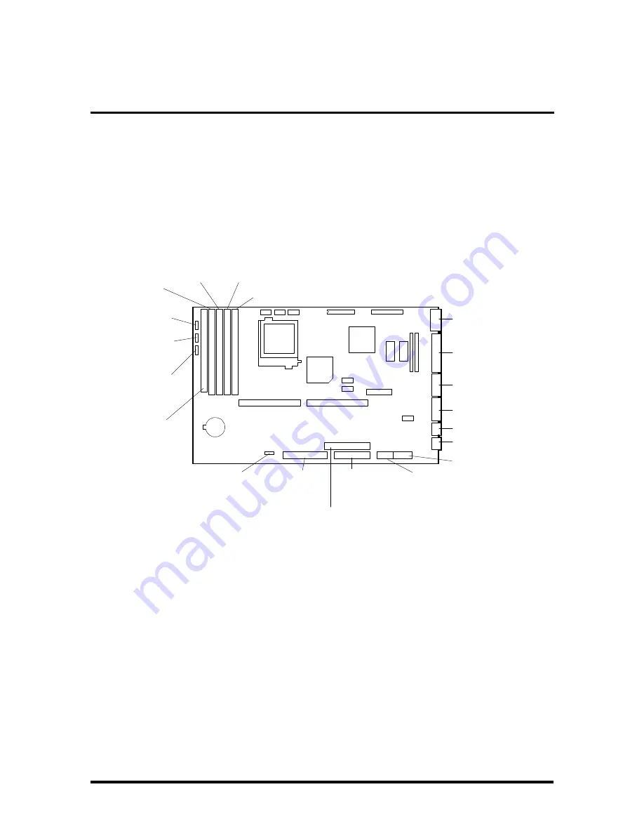
This appendix describes the system board connector pin assignments. Figure Appendix A-1
shows the locations of the system board connectors. Table Appendix A-1 identifies the con-
nector function with the connector number. Descriptions of the connectors are provided in
the following subsections. Jumper settings are provided in Section 2, Setup and Operation.
Figure Appendix A-1 System Board Layout
Bank 0
U1
Bank 1
U11
Bank 2
U10
Bank 3
U2
SIMM Sockets
Secondary
Cache
Socket
U49
Power
Lamp
Connector
Hard Disk
Drive Busy
Connector
Reset
Connector
Speaker
Connector
Fast IDE
Connector
Standard IDE
Connector
Diskette Drive
Connector
Power
Connector
Mouse Port
Keyboard Port
Printer Port
VGA Monitor
Connector
Serial Port 1
Serial Port 2
(primary)
(secondary)
Power
Connector
P3
P4
Summary of Contents for PowerMate 466M
Page 10: ...Contents xiii ...
Page 176: ...Connector Pin Assignments A 15 ...


