4-44 Installing Options
6.
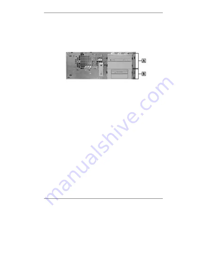
Reinstall the 5 1/4-inch two-device bracket in the bottom bay by
sliding the bracket into the bay until it latches in place. (See the
following figure for bracket and device placement.)
7.
Reinstall all other 5 1/4-inch devices by sliding each into its bay until
it latches in place. (See the following figure for device placement.)
Accessible device placement for a desktop
A – 5 1/4-Inch Bays in Top Bay(s)
B – 5 1/4-Inch Bracket in Bottom Bay
8.
Reinstall any rails and bay covers. The bay cover(s) and rails must be
installed in all empty bays to maintain system integrity.
!
Slide each rail into its slot until it latches in place (see
“Removing a 5 1/4-Inch Accessible Device,” step 6, for details).
!
With the arrows on the sides of the bay cover pointing up, align
the cover with the two rails, and press the cover in until it locks
in place against the chassis (see “Removing a 5 1/4-Inch
Accessible Device,” step 6, for details).
9.
Connect all signal and power cables to the devices.
10.
Remove the logo plate by unclipping its tabs from inside the front
panel.
!
Position the logo plate so it is readable when the chassis is in the
horizontal position.
!
Press the tabs into the front panel until they click in place.
11.
Replace the front panel and system cover (see “System Unit Covers”
earlier in this chapter).
12.
Connect any external options (such as a keyboard and monitor) to the
front or rear of the system unit.
13.
Connect the system unit and any peripheral power cords.


