


Disassembly and Reassembly 3-7
2.
Insert the tabs into their slots and press the front panel up against the chassis until the front
panel locks in place.
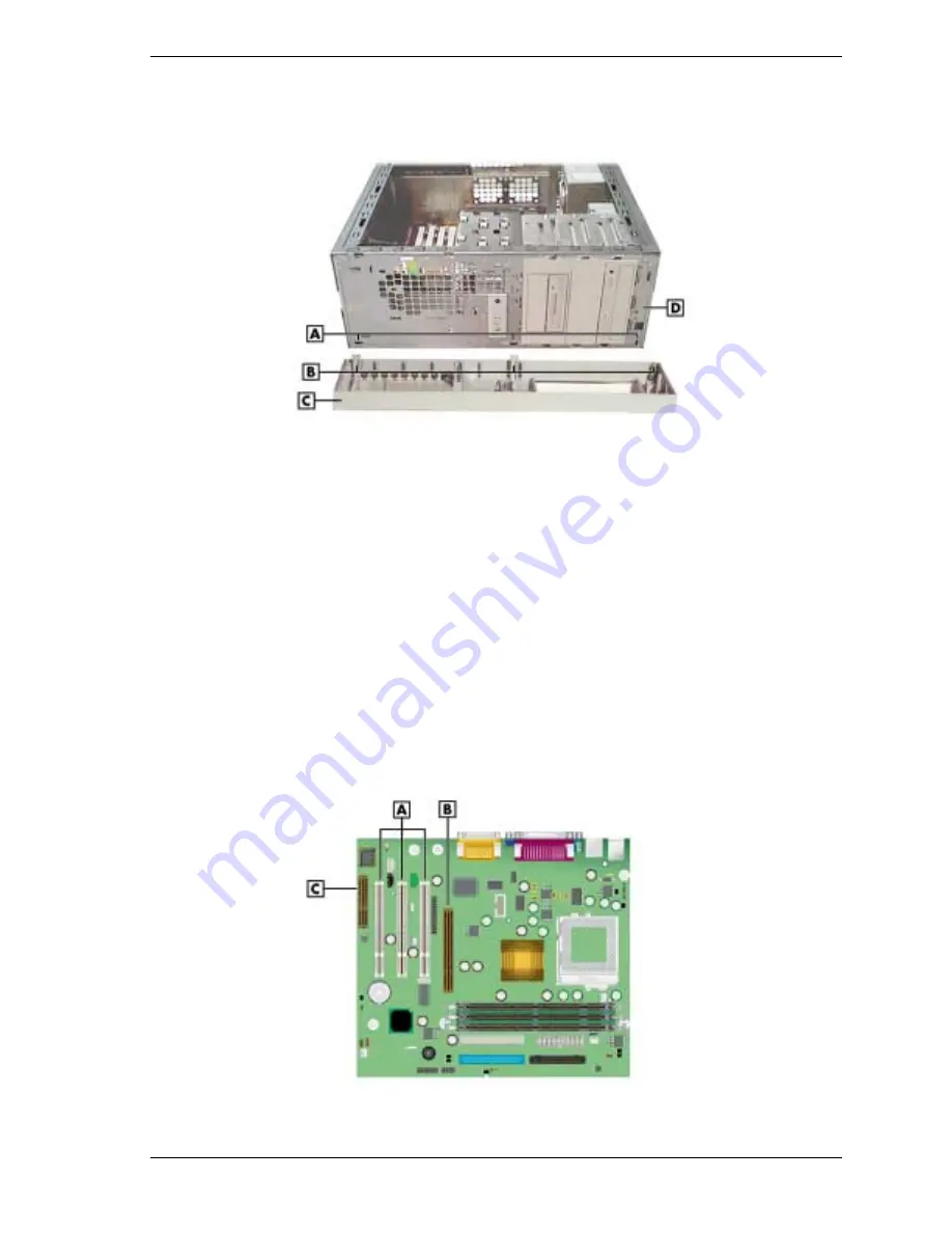
Replacing the Front Panel
A
– Chassis Slots (3)
C
– Front Panel
B
– Front Panel Tabs (3)
D
– Chassis Front
3.
Replace the cover.
Expansion Board
The following sections describe how to:
!
remove and replace the expansion board retainer bar, which secures expansion boards and
slot covers
!
remove and replace expansion boards
!
remove and replace slot covers.
Locations of the expansion board connectors on the system board are shown in the following
figure.
Locating Expansion Board Connectors
A
– PCI Expansion Board Connectors
C
– CNR Board Connector
B
– AGP Board Connector
Summary of Contents for POWERMATE CT 815 - RELEASE NOTES
Page 13: ...1 System Overview Configurations Features Components Software...
Page 106: ...6 Preventive Maintenance System Cleaning Keyboard Cleaning Mouse Cleaning...
Page 109: ...7 Troubleshooting Checklist Diagnostics...
Page 118: ...8 NECC Information Services Service and Support Functions Technical Support...


