3-20
Disassembly and Reassembly
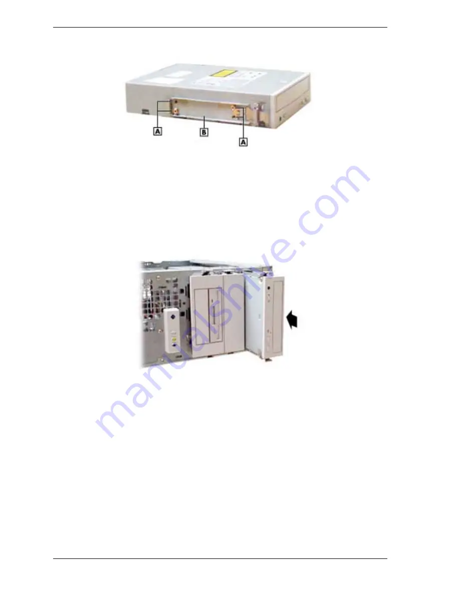
Locating the Device Rails and Screws
A
– Screw or Locking Pin
B
– Device Rail
4.
Determine if the device being installed is a master device or a slave device on the primary
or secondary channel (see the documentation that comes with the device and the table “IDE
Cable Configurations”). Set the device jumpers accordingly.
5.
Position the device so it is right side up for the minitower or desktop orientation (see the
following figure).
Installing a 5 1/4-Inch Device for Use in a Minitower
6.
Slide the device into the empty bay until it clicks in place.
7.
Connect the signal and power cables to the back of the device.
!
Locate an unused signal connector on the primary or secondary interface cable and plug
it into the connector on the back of the device. (See the following figure, “Locating
System Board Cable Connectors,” for IDE cable connector locations.)
!
Locate an unused power cable of the proper length and plug its connector into the
power connector on the back of the device.
8.
If installing a CD-ROM, CD-RW, or DVD-ROM drive and there are speakers, connect the
drive’s audio cable to the CD IN connector on the system board or optional sound board.
9.
Replace the front panel and the cover.
Summary of Contents for POWERMATE CT 815 - RELEASE NOTES
Page 13: ...1 System Overview Configurations Features Components Software...
Page 106: ...6 Preventive Maintenance System Cleaning Keyboard Cleaning Mouse Cleaning...
Page 109: ...7 Troubleshooting Checklist Diagnostics...
Page 118: ...8 NECC Information Services Service and Support Functions Technical Support...


![Lenovo 90B6 [H50-50 ES] User Manual preview](http://thumbs.mh-extra.com/thumbs/lenovo/90b6-h50-50-es/90b6-h50-50-es_user-manual_201023-01.webp)


