


System Board 4-3
Internal Cable Connectors
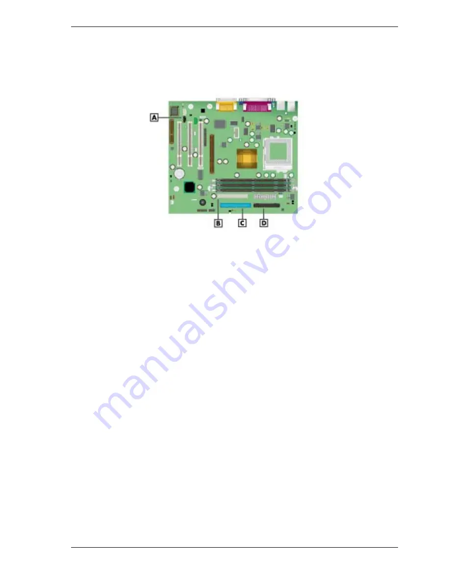
Locations of the internal cable connectors on the system board are shown in the following
figure.
System Board Internal Cable Connectors
A
– CD Audio In
C
– IDE Primary Connector
B
– IDE Secondary Connector
D
– Diskette Drive Cable Connector
Jumper Settings
The following sections provide the names and locations of jumpers on the system board, and
provides procedures for changing a jumper setting.
Locating Jumper Blocks
The system board has six configuration jumper blocks:
!
CMOS Clear JP18
!
BIOS Recovery JP15
!
Rear USB Device Wake Up JP1
!
PS/2 Keyboard at Power On JP3
!
Front USB Keyboard Wake Up JP31
!
Save to RAM JP4.
Use the following figure to locate the jumper blocks on the system board.
The factory-set jumper settings are included in Section 2, “System Configuration.”
Summary of Contents for POWERMATE CT 815 - RELEASE NOTES
Page 13: ...1 System Overview Configurations Features Components Software...
Page 106: ...6 Preventive Maintenance System Cleaning Keyboard Cleaning Mouse Cleaning...
Page 109: ...7 Troubleshooting Checklist Diagnostics...
Page 118: ...8 NECC Information Services Service and Support Functions Technical Support...


